Animation Editor
Table of Contents
The Animation Editor hosts both the Keyframe Animation and State Machine functionality. It is divided into three different views which will be explained in the following. For general information on animations in Ventuz, see Animation and State Engine.
To access each of the three views, click the respective button in the top row of icons:
| Icon | Name | Description |
|---|---|---|
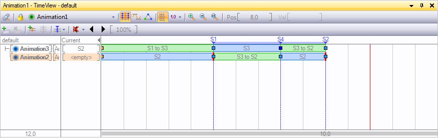
 | Time View | The Timeline View offers a simplified representation of all keyframe animations in the form of duration bars. Press T to switch to the Time View. |
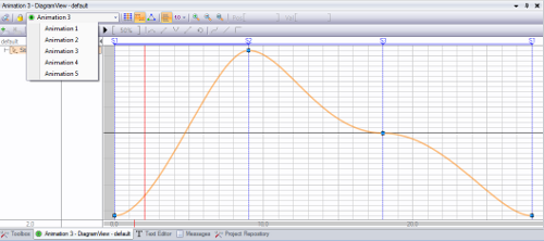
 | Diagram View | The Diagram View offers the classic view for editing bezier-type animation curves. Press D to switch to the Diagram View. |
 | Logic View | The Logic View is used to edit Soft and Hard States including their keyframe values as well as the behavior and methods for controlling and playing back the animations. Press L to switch to the Logic View. |
Each scene can have any number of independent animations where each animation can contain multiple properties being animated. To change the current working animation, use the drop down box at the top left corner of the Animation Editor. The animations are identified by its name.
Keyframe Animation
Keyframe Animation is the most commonly used technique to animate objects in 3D. Instead of specifying the value of a property for each frame of the animation, values are only set at important points in time, so called keyframes. All required intermediate values are generated automatically by interpolating between the keyframe values. This is much less time consuming and produces better results than hand-editing every frame. Still, proper keyframe animation is not an easy task and is an art form in itself. However, Ventuz's keyframe animation system uses many of the same conventions 3D modelling packages use and the interested reader will find an abundance of tutorials and books on 3D animation theory available on the internet that are applicable to Ventuz.
Time View
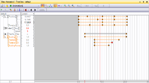
The Time View contains three areas: The left row contains a tree hierarchy of Animation Channels, one channel for each property that is animated by this Keyframe Animation node.
To animate a property, left-drag it from the Properties Editor to the Animation Editor or CTRL + left-click the property name. To create an additional Animation, drag a Keyframe Animation node from the Toolbox to the Content Editor.
When dragging a property into the Animation Editor, a new Animation Channel is created for that property. A group with the node name is added, beneath that a group with the property category name and finally the entry with the property name. It is important to keep in mind that the name of all those items or the structure can be completely changed by the user. It is just a logical grouping that has no effects on the values generated.
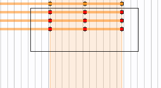
The channel list is used to select the active channels that operations like keyframe insertion operate on. To select a channel, click  on the channel name and its background will be shaded red. To select multiple channels, press and hold CTRL while selecting channels.
The right area shows the timeline for the animation and where the keyframes for each property are set. By clicking into this area, the current time (represented by a red vertical line) can be changed and as long as the left button remains pressed, the animated property will have the value defined at that point in time of the animation instead of the following the global time of the animation. By dragging left and right , the user can scrub through the animation. The current value at the time, the red line is set to, is shown in the column between the tree hierarchy and the timeline.
Initially, a property has no keyframes. To define a new one, set the current time (red line) to a point in time and then press the Add Keyframes button. Next, while staying at the same point in time, enter a value by double-click on the current column. Without a keyframe, the user can enter a current value but it will not be saved. Keyframes can be removed by clicking on the keyframe and then pressing Delete on the keyboard.
Adding of keyframes is only done for the selected property channels. If nothing happens when pressing the add keyframe button, make sure something has been selected by left-clicking in the tree structure in the left column of the Animation Editor to select one or more channels.
When clicking on a keyframe, the Properties Editor will show additional information about the keyframe. Those will be discussed once the Diagram View section has been introduced.
Multiple keyframes can be selected by either SHIFT+ on individual keyframes or by SHIFT+ outside any keyframe and dragging to start a rectangle selection. Selecting multiple keyframes will draw range borders in the timeline from the very first to the very last selected keyframe. These range borders can be used to scale all selected keyframes. Move the mouse cursor over the range borders until the scale handle is displayed and left-click and drag the mouse to scale in any direction.
The  is used for navigation purposes. Pressing and dragging shifts the section of the time line that is visible. Moving the wheel up or down will zoom in and out respectively.
Diagram View
While the Time View is mainly for organizing a large number of keyframes in an efficient way, the Diagram View visualizes the actual change in values over time in the form of function curves.
Time View and Diagram View share much of the same functionality which will not be repeated here. However note that only the curves of selected animation channels are shown in Diagram View.
Keyframes can be added, modified and deleted in the same way as it is done in the Time View. What is unique to the Diagram View is that the interpolation behavior of the curve between the keyframes can be adjusted.
There are three ways the values between two keyframes can be interpolated. This type can be set for each segment of the curve individually by selecting the keyframe at the beginning of the segment and then choosing the appropriate interpolation type.
| Icon | Name | Description |
|---|---|---|
 | Jump | Between two keyframes, the value is equal to that at the first keyframe and abruptly jumps to the new value when it reaches the second keyframe. |
 | Linear | The curve follows a straight line starting from one keyframe to the next. |
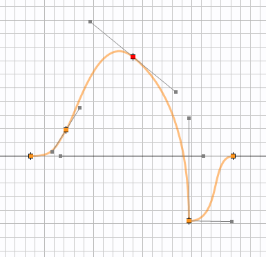
 | Smooth | The tangents of the curve at both keyframes of a segment can be set by the user. The curve will interpolate smoothly between the two keyframes while respecting the tangents specified. |
When setting a curve segment to smooth interpolation, tangent handles will appear at both sides of the keyframe which can be dragged to influence the curve. Such a keyframe can have one of four locking types that describe the relation between both handles.
| Icon | Name | Description |
|---|---|---|
 | Free | Both tangents are completely independent of each other. |
 | Direction | Both tangents will be forced to have the same direction but can have different length. |
 | Mirror | One tangent will be the mirror image of the other. |
 | Fully Locked | Both tangents will have the same length and direction. |
Logic View
Finally, the Logic View is used to define states and the transitions between them. For a discussion on the types of States and the State Engine in general, please refer to Animation and State Engine.
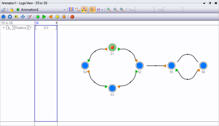
States are represented as circles in Logic View and as timeline markers in Time View and Diagram View. Filled circles are used for Hard States and rings for Soft States. Each state has exactly one representation in Logic View regardless of how many slices are associated with it.
State Editing
New Hard or Soft States can be created by using the respective buttons in either the Logic View or one of the other views. A Hard States keyframe values will be set to the current value in the animation channels. To delete a state, select it by left-clicking on the circle and then DELETE. If a Hard State is selected, a blue box will be drawn around the current values column indicating that any change in this column will be stored in the respective keyframe. Finally, double-clicking on the state name allows the user to rename the state.
A State can be assigned one of a number of Types by selecting the State and changing the type property in the Property Editor.
| Type | Icon | Description |
|---|---|---|
| Normal |  | This is the default type, no special semantics are associated with this state. Press N to turn the selected state into a Normal state. |
| Begin |  | Triggers the BeginReached event of the Keyframe Animation Node. |
| Begin Default |  | Same as Begin but this state is jumped to when the user triggers the Begin method of the Keyframe Animation Node. There is always exactly one default begin state in a State Logic. Press B to mark the selected state as BeginDefault state. If another state was the BeginDefault it turns into a Begin state. |
| End |  | Triggers the EndReached event of the Keyframe Animation Node. |
| End Default |  | Same as End but this state is jumped to when the user triggers the End method of the Keyframe Animation Node. Press E to mark the selected state as EndDefault state. If another state was the EndDefault it turns into a Begin state. |
| Present |  | Special State Type only used in the context of the Slider Manager. Please refer to the Slide Manager documentation for more information. Press P to mark the selected state as the Present state. |
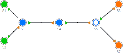
State Connections
Connections between States are the visual representations of parts of an animation timeline. These connections are automatically created if two or more States are added in Time View or Diagram View. To manually create a connection between two States, click  on a State and drag on top of another state (or the same state). During the drag&drop operation, a black arrow indicates the direction of the connection.
Creating a State connection between two States in Logic View will automatically create an associated keyframe animation called a Slice. To access the associated animation for a connection, double-click on the connection to switch to either the Time or Diagram View (whichever was used last).
When a new connection is created, Ventuz tries to add the new animation to a previous one instead of creating a new Slice. This is possible if an older Slice ends with the State the new connection starts from. While this seems inconsistent to the advanced user, it helps present a uniform timeline for linear State Logics and thus ease the transition for new users.
Deleting a connection between two States is not possible in Logic View as it would also delete the entire keyframe animation. To delete a connection, the State markers have to be deleted in Time View or Diagram View.
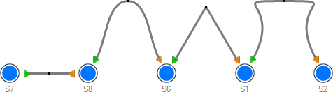
Layout and Annotations
In order to make an animation logic easier to understand, the states can be rearranged and documented in the Logic View. Clicking a State and dragging it moves the state to a new location. The curvature of a connection can be changed by again clicking and dragging the square in the middle of a connection. When pressing CTRL and then continuing to drag , the curve shape can further be changed.
Annotations containing descriptions or instructions can be added by pressing the Create Annotation button. They can be moved by clicking and dragging and edited by double clicking on the Annotation.
Playing Animations
After introducing all the views, it is easy to forget one important fact:
All work in the Animation Editor changes information inside a Keyframe Animation node that exists in the scene. To add a new Animation, a Keyframe Animation node has to be added, to delete an Animation, the respective node has to be removed.
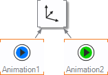
Therefore the methods and information to control and play an animation are located as properties in the Keyframe Animation Node, not the Animation Editor. There are two variations of a Keyframe Animation Node, depending on whether the animation has also a State Logic or not. This is also visualized in the color of the node icon: A green node has no State Logic where a blue node has one.
As stated before, all animation timelines contained in an animation node are by design independent of the global scene time. There is no one "start time" or speed of animation that applies to the whole scene. So in both cases, the animations contained in the animation node have to be assigned some form of "start trigger" and speed indicator.
Stateless Animation
Without a State Logic, a Keyframe Animation Node has a single Input Property called Control. Any of the Control Nodes can be bound to this, thus associating either a time or progress value with the animation. For more information and examples, see Control Nodes.
With State Logic
When a Keyframe Animation Node has a State Logic, there is an alternative way to trigger the animation. A single state can be designated as the Begin ![]() and another as the End
and another as the End ![]() of the animation logic. A single state can represent the Present State
of the animation logic. A single state can represent the Present State ![]() to mark to point where the entire graphics is visible. This is done by selecting the state in the Logic View and changing its type in the Property Editor or by pressing B, E or P. Triggering the Begin, End or Present Input Method will make the state engine assume the respective state as the currently active state in the animation. They are primarily used to reset the State Machine.
to mark to point where the entire graphics is visible. This is done by selecting the state in the Logic View and changing its type in the Property Editor or by pressing B, E or P. Triggering the Begin, End or Present Input Method will make the state engine assume the respective state as the currently active state in the animation. They are primarily used to reset the State Machine.
The Next/Prev methods can be used to steer the direction in which the State Machine should continue. Each State can have one connection marked as the direction to follow when the State Machine is at that State and the Keyframe Animation Nodes Next method is triggered. The same is true for the Prev method. If done correctly, the user does not have to know anything about the individual states or even how many exist. He just decides if he wants to go forward or backward in his presentation.
When a connection is made between two States and a next/prev connection has not been assigned, they will be automatically. To explicitly assign next or prev, select the Keyframe Animation node in the Content Editor and drag the method on to the start/end of the State Connection. To revoke the assignment, select the State Connection and reset the Begin or End rule in the Property Editor. The author can even add new methods to the State Logic by using the Custom Model on the Keyframe Animation node.
The Begin/End/... buttons in the toolbar of the Animation Editor are not for assigning states but triggering them. Pressing one of those buttons has the same effect as triggering the method in the Property Editor.
Nested Animations
Due to the modular approach of Ventuz, even the controlling aspects of a State Logic can be animated by another Keyframe Animation. Drag the Control Input Property of one Keyframe Animation node containing a State Logic animation onto another Keyframe node.
Embedded keyframe animations behave much the same way as regular keyframe animations. Keyframes are now representations of States and the connections between them represent the embedded keyframe animations. Double-click or click on a keyframe reveals the State and Connections dialog. Select either the State you want to assign to a keyframe or the State Connection to be used between two keyframes. If a State is selected, the animation will hold the State values until the next keyframe. If a State Connection is selected, the embedded keyframe animation defined by its embedded States will be played back.
In order to avoid discrepancies with jump commands and general playback when using embedded animations, it is recommended to always use Hard States.
Held States are marked in blue and State Connections are marked in green. If State Connections have been selected and the embedded animation logic does not define them in a fluid rundown, a jump in the animation will occur. These breaks in an embedded animation do not necessarily have to be an error and can be used nevertheless. These breaks are marked with a red bar at the corresponding keyframe.
Feedback
Both States and Connections can be assigned IDs and names by selecting them in the Logic View and then changing the appropriate values in the Property Editor. This information is passed to the Output Properties of the Keyframe Animation Node when the State Machine changes States. The ID and name values propagated by the State Machine can be used for more complex automation when bound to other nodes.
Since simply dragging a property onto the Keyframe Animation Node starts a new Animation channel, a special technique has to be used to bind the output values of the State Machine to other nodes: Drag the input property on to the Keyframe Animation Node in the Content Editor, hold the mouse button and wait for a few seconds. The Property Editor will switch to the Keyframe Animation. Drag the property over the outputs button, wait, drag to the output property and release.