How To Create a God Ray Shader
Table of Contents
This How To will show you the steps required to create a simple "god ray" shader. While this cannot teach you HLSL itself, it might be a good starting point for learning how to port existing shaders to Ventuz.
Introduction
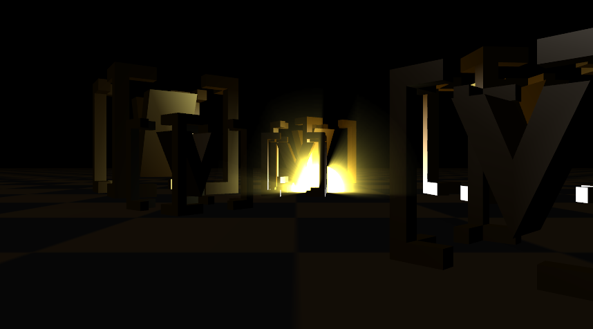
A "God Ray" shader is a classic image space post processing shader. It mimics the light streaks emanating from a bright light source when it is surrounded by a participating medium such as mist. The shader - from a top-level perspective - consists of two elements: A geometry that represents the light source as well as a number of occluders that can block the light of sight towards the light source.
Algorithm
The basic algorithm is rather simple: First, render the part of the light source geometry that is not occluded, then blur it from the center of the light source outwards to produce the characteristic light streaks. All this is done in 2D image space instead of the 3D world as computing how the light rays propagate in the medium would be way to expensive for realtime rendering. So the goal is to look cool, not be physically correct!
Inventing a new shader effect from scratch is quite a daunting task. Luckily, shader technology has been used on graphics cards for a decade now and there is an abundance of books and internet tutorials. So instead of trying to re-invent the wheel, your natural instinct should be to do a search in the standard literature:
- The Shader X series of books
- The GPU Gems series of books
- Development portals of the main graphics card manufactures
- A Google search
While one rarely finds an algorithm that is plug-and-play, all we need is the basic algorithmic idea, some linear algebra, general understand of the inner workings of a graphics card and, well, knowledge of our target language: HLSL.
Since there is no right or wrong with shaders and it is a playing field of mainly professional developers and computer graphics students, the quality of published algorithms varies a lot. Keep in mind that the authors may one have addressed a special use case like for example using exactly one light source and without support for textures. What additionally makes it tricky is that you are only looking at one part of the equation: The shader code which represents the rendering algorithm. However, each shader has input parameters that have to be provided by the hosting application, a part which is often omitted in shader discussions.
So let's get back to our God Ray shader. A simple yet nice explanation can for example be found here: Fabian Sanglard's Non-Blog. There is a video, an explanation and even source code. However, there are two main problem's:
- It is in GLSL, the OpenGL Shading Language, not HLSL.
- How to integrate the code in a form that it can be used inside Ventuz?
Conversion to HLSL
So let's have a look at the original GLSL shader code. Since all the credits go to Fabian, we won't duplicate the code here but instead refer you to the original site. If you like his shader, you might consider dropping him an email and thanking him for all the effort he obviously put into it.
If you have any knowledge of GLSL or shader at all, it should be pretty straight forward: First, there are a number of parameter declarations, most of which we will translate to user adjustable Ventuz properties later on. There is also an input texture and a constant declaration, the former being the non-occluded part of the light source geometry and the latter the number of samples to be used for each pixel. We'll get back to that later on.
So grab an HLSL Node and let's going: Ventuz automatically inserts a shader skeleton template with a single render pass for you. Above the vertex shader code, add the parameters we found in the GLSL code:
float Density;
float Weight;
float Decay;
float Exposure;
float2 LightPosition;
texture OcclusionMap;
sampler OcclusionSampler = sampler_state
{
  texture = <OcclusionMap>;
};

static const int NUM_SAMPLES = 100;
The only slightly interesting part here is the texture/sampler declaration but that directly comes from the documentation of the HLSL Shader Node.
Vertex Shader
The main body of the GLSL function doesn't do anything with vertex positions and therefore clearly belongs into the pixel shader part of our HLSL shader. But without geometry after the HLSL node, the shader will never be triggered, so what is the geometry used here? Since this is a screen space effect, the obvious choice would be to use an Overlay Rectangle. This way every pixel on the screen will be hit by the geometry exactly once and we even have nice texture coordinates available.
However, we are going to use a Rectangle instead for two reasons:
- The Overlay Rectangle internally does a lot of DirectX calls to always be screen-aligned, something we can do much easier in the shader ourselves.
- The Overlay Rectangle will produce an incorrect alpha mask which leads to problems when producing a broadcast key signal.
So what do we know? By default, the Rectangle has UV coordinates from 0 to 1 and has vertices at (-0.5,-0.5,0.0), (-0.5,0.5,0.0), (0.5,-0.5,0.0), (0.5,0.5,0.0). We want to map those to the full screen, so keeping the standard World-View-Projection matrix model in mind, we want the rectangle to be mapped to (-1,-1,0), (-1,1,0), (1,-1,0), (1,1,0). We also will need the interpolated texture coordinate of each pixel in the pixel shader, so we extend VS_INPUT to also contain the texture coordinate.
struct VS_OUTPUT
{
  float4 Position : POSITION;
  float2 TexCoord : TEXCOORD0;
};

VS_OUTPUT VS( VS_INPUT Input )
{
  VS_OUTPUT Output;
  Output.Position.x = Input.Position.x * 2.0f;
  Output.Position.y = Input.Position.y * 2.0f;
  Output.Position.z = 0.0f;
  Output.Position.w = 1.0f;
  Output.TexCoord = Input.TexCoord;
  return Output;
}
Pixel Shader
Now on to the pixelshader. This is pretty much a 1:1 translation from GLSL to HLSL:
float4 PS( VS_OUTPUT Input ) : COLOR
{
  float2 deltaTexCoord = (Input.TexCoord - LightPosition.xy);
  deltaTexCoord *= Density / NUM_SAMPLES;
  float4 color = tex2D(OcclusionSampler, Input.TexCoord);
  float illuminationDecay = 1.0f;
  for (int i = 0; i < NUM_SAMPLES; i++)
  {
    Input.TexCoord -= deltaTexCoord;
    float4 sample = tex2D(OcclusionSampler, Input.TexCoord);
    sample *= illuminationDecay * Weight;
    color += sample;
    illuminationDecay *= Decay;
  }

  return color * Exposure;
}
That's it, you completed the shader. We'll change it a bit later on, but that's basically it. For each pixel, we compute the vector from the pixel to the screen space position of the light source and go along that vector in NUM_SAMPLES steps. Each step, we look up the color value in our texture and add it to our result, weighted by various factors. The more steps actually are inside the rendered light source geometry, the brighter the final pixel will be.
The NUM_SAMPLES constant is quite important for achieving a good quality with this shader. The larger the glow around the light source you want, the higher this needs to be. Or the other way round: If you have a particularly large glow, you will experience color banding artifacts if that number is not high enough. However, the number of iterations done in the for loop of course directly relates to the time the graphics card will spend inside the shader. So more samples equates to better quality but slower performance.
Blending
There is one important step left: We need to make sure that the correct Alpha Blending is set up. We could do this with Ventuz nodes, but we'll do it in the shader instead. Modify the pass in your technique:
technique Tech1
{
  pass pass0
  {
    vertexshader = compile vs_3_0 VS();
    pixelshader  = compile ps_3_0 PS();
    AlphaBlendEnable = true;
    BlendOp = Add;
    SrcBlend = One;
    DestBlend = One;
  }
}
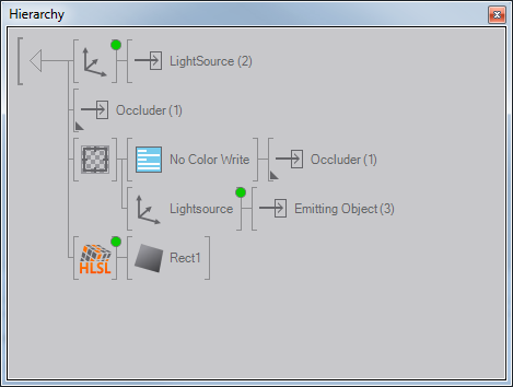
Scene Hierarchy
Now we need to create the setup to use the shader correctly. The main task will be to create that input texture which contains the masked light source geometry. Let's start by putting the HLSL node into a Hierarchy Container. Rename the existing Output to "Occluder" and add two additional ones: "Lightsource" and "Emitting Object". We also add the aforementioned Rectangle behind the HLSL shader node.
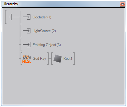
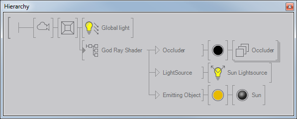
Let's step out of the Container for a moment. We will use the Occluder output for all parts of the scene that should occlude the lightsource. At the Lightsource output, we'll add a Point Light. This is not strictly necessary, but the shader will just create the streaks, the other geometries in the scene will not be shaded by our shader. So we add a true light source at this output and move consistently with the lightsource geometry we will use to create the god ray effect. Speaking of which, at the Emitting Object output we'll add a Sphere and put a Color node in front of it. Set that to a nice yellow color.
Masked Light Source
Back inside the container. Add a Render Target above the HLSL node. We need to render the light source geometry but masked by the occluders, a typical job for a stencil mask. However, we'll do something differently here: We use the Z-Buffer instead. Behind the Render Target add a Render Options node and place the occluder output behind it. Deactivate the RGBA channels for Color Write (if you don't see those properties, you might have to select the Render Options node in the Content Editor). In a second branch behind the Render Target, add an Axis and put the Emitting Object output behind it.
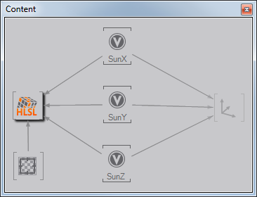
The Axis is supposed to give the user the capability to move the light source from outside the container. We will need the position in the HLSL shader node as well, so add three Float Variable nodes, label them X, Y, Z and expose their properties. Connect the outputs of those variables with the position properties of the Axis.
Finally, bind the Render Target output to the Texture parameter on our HLSL shader node.
The Lightsource
This renders the God Ray light streaks, but not the Lightsource or the Occluders. So add an axis above the Render Target. Move the Lightsource output behind the axis and connect the Axis' position properties to our three floating variables. Now select the Occluder output and press Ctrl+Shift while dragging the Output below the Axis. This will create a node reference.
Summary
So from the top:
- Render the Lightsource translated by the exposed X,Y,Z position values
- Render the Occluder. This is the normal rendering of your scene.
- Activate the Render Target. First render the Occluder just to the Z-Buffer and then render the translated Emitting Object in the usual way.
- Activate the HLSL shader and render the Rectangle.
Revisiting the Shader
There are a couple of things we'll do to improve our shader. First, change the LightPosition from float2 to float3 and add SaS annotations to all the end-user shader parameters. Having proper min/max values will make it much easier for the user to create great results.
float Density
<
  float SasUiMin = 0.0f;
  float SasUiMax = 1.0f;
  float SasUiSteps = 0.01f;
> = 1.0f;
float Weight
<
  float SasUiMin = 0.0f;
  float SasUiMax = 1.0f;
  float SasUiSteps = 0.01f;
> = 0.5f;
float Decay
<
  float SasUiMin = 0.0f;
  float SasUiMax = 1.0f;
  float SasUiSteps = 0.01f;
> = 0.5f;
float Exposure
<
  float SasUiMin = 0.0f;
  float SasUiMax = 10.0f;
  float SasUiSteps = 0.01f;
> = 1.0f;
Now we are going to change the actual shader a bit. The original source code specifies the position of the Lightsource in screen-space. However, specifying it in 3D world space would make it much easier for the user and would allow us to sync it with the position of our point light.
So we are going to compute the 2D screen-space in the vertex shader based on the 3D parameter. Extend VS_OUTPUT to contain a light position and compute it in the vertex shader:
struct VS_OUTPUT
{
  float4 Position : POSITION;
  float2 TexCoord : TEXCOORD0;
  float2 LightPos : TEXCOORD1;
};

VS_OUTPUT VS( VS_INPUT Input )
{
  ...

  float4 lightPosScreenSpace = mul(float4(LightPosition, 1.0f), WorldViewProjection);
  lightPosScreenSpace /= lightPosScreenSpace.w;
  lightPosScreenSpace.x = 0.5f + lightPosScreenSpace.x / 2.0f;
  lightPosScreenSpace.y = 1.0f - (0.5f + lightPosScreenSpace.y / 2.0f);
  Output.LightPos = lightPosScreenSpace.xy;
  return Output;
}
In the pixel shader, change the first line to:
float2 deltaTexCoord = (Input.TexCoord - Input.LightPos.xy);
If you are wondering if that's not a lot of unnecessary work to do for each vertex, you can use the Disassembly viewer inside the Shader Editor. The DirectX effect compiler actually puts the majority of the vertex shader into a so called pre-shader. The pre-shader is only executed once for each mesh and what calculation remains per vertex is just 4 instructions. So we're more than fine...
Finishing Up
All that is left for you is to expose the right values to the outside of the container. We'll want to have:
- X, Y, Z position of our Lightsource
- Density, Weight, Decay, Exposing of our HLSL shader.
After all that work, we now have a nice and easy to use God Ray shader. For debugging purposes, it's nice to add additional techniques inside the shader. For this shader, two techniques are quite handy:
- No Rays: a technique that shows the scene including the light source geometry but without the rays
- Rays only: a technique that shows just the rays in front of a black background.
It is usually best to do such "alternatives" as additional techniques. Some people rather use boolean parameters, but those actually extend the vertex/pixel shader programs and thus make the shader slower. We won't be going into details on how to implement those techniques but both amount to knocking out a few lines of code or overwriting an alpha value here and there.
Conclusion
Wow, that was quite a bit. As you can see, converting the actual shader code was quite straight forward. The part that most shader tutorials/books unfortunately leave out is providing the infrastructure for the shader to actually work. However, with some practice, there are a lot of re-occuring patterns. For example, using a Rectangle to produce a screen filling output is a technique common to a lot of shaders.
If you are interested in shaders of similar complexity, have a look at the ShaderX 3 book. While you won't be able to copy-&-paste the shader code into Ventuz, you will probably find more than enough ideas for your shaders in that single book. ShaderX 2 is interesting but rather more low-level while ShaderX 4 and beyond tend to contain shaders that are of limited practical use in a Ventuz production.
A final warning: A lot of shader examples do contain programming errors or might not be exactly what you need. Also, some hosting application might provide matrices in a transposed form and so on. Definitely check out the tips and tricks at the end of the HLSL shader node documentation.