Multi-Display Setups and Output Shaping
Table of Contents
One of the major features of Ventuz is its capability to render to multi-display setups. Common setups are the use of a 3x3 wall of LCD displays or two or more projectors arranged in a horizontal fashion. With the inclusion of shaping functionality, even non-planar surfaces can be projected on.
There are two general types of setups: Setups that use a single machine with multiple outputs or a cluster of machines, each rendering a portion of the scene.
Problem
The general problem can be formulated as follows:
Given a number of output displays in an arbitrary orientation and position to each other, render the content of a Ventuz Scene such that the output appears consistent to the user.
A number of issues arise from this problem:
- Gaps: When using any kind of LCD display, two displays cannot be joined pixel to pixel because of the frame around the display panel. The portions of a scene that are rendered in each display must therefore have some gap between them as well, otherwise the output will be distorted. For example, a sphere lying on the boundary between to displays would appear stretched if one display continues at the next pixel of where the previous display left off.
- Overlaps: When using multiple projectors, the obvious idea seems to align each output pixel perfect next to the other (often called Image Butting). However, in practice it is almost impossible to achieve a consistent output with this technique. For one, calibrating a projector output 100% correct up to pixel alignment takes a lot of time to say the least and preserving it (temperature changes, vibrations, someone sneezing in the vicinity...) is even worse. Assuming this could be done, it is virtually impossible for two projectors (even of the same brand and model) to produce precisely the same color/intensity output. In practice, projectors are set up so that there is an overlap between neighboring outputs. Both overlaps are blended one into the other to produce an unnoticeable transition.
- Orientation: The orientation of pixels in the output device may not be the same as that of the result one wants to achieve. For example, a number of displays may be bolted to a wall rotated by 45 degrees but lined up horizontally with the goal to show one scene that is aligned with the floor.
- Projection Surface: The surface projected on may not be planar. It may be part of a dome or a large canvas that is curved.
As a precaution, make sure that your output devices (LCD/projector) are calibrated to produce exactly the same colors to as close a degree as is possible. If, for example, one projector is older than the other, there is a chance that the one projector will display a full red differently than the other projector. Those kinds of problems must be compensated in the hardware or the graphics card driver.
Setup
Ventuz has one single Renderer Output Window, so all output devices have to be assigned a portion of that window. This is done by running Ventuz in fullscreen mode and setting up the Graphics Card Driver to create one big desktop spanning all outputs instead of separating each output. Combining multiple hardware outputs to create one virtual desktop is called Display Group for AMD Graphics Cards or Span Mode for nVidia Graphics Cards. Once this has been set up, the challenge is to render the correct content into each portion of the desktop.
Please consult your graphics card and driver manual for more information on how to setup display groups/span mode as this part is completely independent of Ventuz.
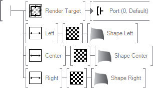
The general idea of multi-display output is to render the content of a Ventuz scene to a texture using the Render Target Node. This texture is then mapped onto a Shape Surface Node which is positioned on the desktop to match a single hardware output. Each of the Shape Surfaces can then be adjusted independent of each other to produce the correct output result.
Display Wall with Gaps
The example below shows a simple Ventuz Hierarchy to split a scene into three different outputs. Each display is 1920x1080 so the Render Size in the Project Proerties has been set to 5760x1080. The actual content is stored in a separate scene which is loaded via a Scene Port Node and rendered into a Render Target Node.
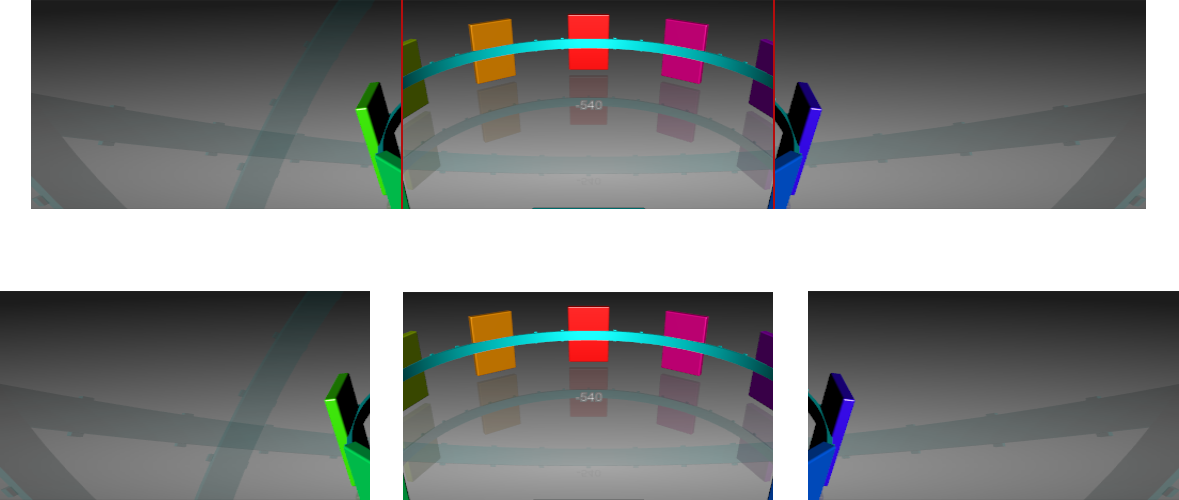
For each of the outputs, a Viewport has been added. Each of it has its Width restricted to one third and its position so that left is at 0, center at one third and right at two thirds. This way each viewport exactly matches the region of the desktop that belongs to one of the hardware outputs.
Behind each of the Viewports is a Texture Node which input is bound to the output of the Render Target. Finally, a Shape Surface is added behind each Texture Node to actually render the texture produced by the Render Target. Each of the three Texture Nodes has a 2D Mapping bound to it. By setting the ScalingX property to 3 for all mappings, adjusting the left mapping PositionX to -1 and the right mapping PositionX to +1, one consistent image is produced.
For reasons which will become obvious later, one should also give Shape Surfaces names which make them easy to identify.
The final part is to compensate for the gap between the displays. Let's assume the gap is 120 pixels each which leads to a total size of 6000 pixels for the virtual width of all three displays as they are positioned side by side. The scaling on all mappings has to be changed to 3.125 (width of whole output divided by the width of the display, so 6000/1920) to compensate for the larger output area. The position of the left and right also has to be compensated to plus and minus 1.0625 (one to shift one display length plus the size of the gap in texture space, so 1 + 120/1920). For four displays this would be 4.1875 for scaling (8040/1920), the shift of the outer mappings to 1.59375 (one and a half displays plus one and a half gaps) and 0,53125 (half a display plus half a gaps).
Since Catalyst Version 10.3, Bezel compensation can also be done on the driver level for ATI graphic cards. For more information, see your driver manual.
Projectors with Overlap
The situation for projectors and overlaps is similar to the example above, except for one thing: The overlapping region receives light from two projectors and therefore appears twice as bright. That will be discussed in the second half of this section, but first the general setup:
Let's assume each projector again is 1920x1080 and each overlap is 25% of the width. The total size is therefore 4800x1080 (three times the width minus two times 25% lost in the overlap). The scaling factor boils down to 2.5 and the shift to 0.75 (one display width minus 25%).
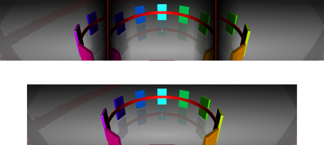
What remains is to create blend regions for each shape such that the respective overlap regions blend into their neighbors.
Since Ventuz is usually running in fullscreen mode when doing this, all functionality to manipulate Shape Surfaces is not in Ventuz but in the separate Ventuz Remote Shape Tool. This way shaping can be done from any other machine connected to the same network.
The Remote Shape Tool is used to connect to running Ventuz instances and manipulate the Shape Surfaces contained in them. To connect to a machine, press the green Add Button, then click one time on the created list entry to rename it. Enter the address of the target machine or localhost for the local machine. When unfolding the list entry, the Remote Shape tool will scan the specified machine and present a list of all Shape Surfaces in the scenes currently open. By double-click on any surface, the respective shape is opened.
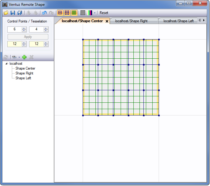
The Remote Shape Tool visualizes both the shape's geometry and the blending regions. To adjust the blending, move the mouse cursor over any of the four yellow soft-edge regions and press  to open the edge context menu.
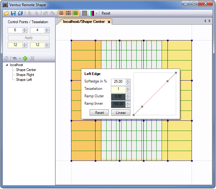
The above screenshot shows both the left and right edge adjust to 25% width for the center shape with a linear alpha gradient. By increasing the tessellation and moving the handles in the diagram on the right, the characteristic of the soft-edge can be adjusted. Add a 25% soft-edge to the right edge of the left shape and the left edge of the right shape to complete the setup.
Surface Shaping
When the surface projected on is non-planar, the output image will appear distorted unless the projector has been adjusted to compensate for it internally. The capabilities for shaping the output are usually limited to simple skewing or stretching except for high-end projectors. Even then, the available options may not suffice.
To solve this problem, Ventuz can shape its output before it gets to the projector. As before, a rectangular region is assigned to the hardware output which feeds a projector. By changing the geometry of the Shape Surface Node, the signal going to the projector can be adjusted such that it compensates for the deformation of the projection surface.
The geometry of each Shape Surface is based on an underlying Bezier surface. A Bezier surface is a mathematical description of a smooth surface by using control points. The step of generating triangles and vertices from that surface is independent of defining the shape and form of the surface via the control points.
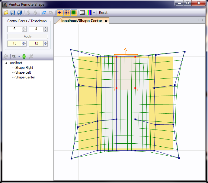
By dragging the control points (blue dots), the shape can be adjusted in an intuitive way. If multiple control points are selected (via selection box with  or clicking with pressed SHIFT key), it is possible to rotate, scale the selected control points and to perform a corner pinning. Just move the corners, edges and the top handle of the selection box. If the CTRL key is pressed during corner pinning, the transformation is locked to the X or Y axis.
Both the resolution of the Bezier surface control grid and the final polygonal tessellation can be increased/decreased with the value boxes in the upper left of the user interface.
Producing a correct shaping is a process of visual inspection, trial-and-error and manual tweaking that is mostly dependent on the skills of the person doing it. Do not underestimate the amount of time required for this step.
In general, one should start with a correct layout of the scene in Ventuz as described in the previous sections. Next use the projectors capabilities to adjust for distortions in the output and then use the Remote Shape Tool for any further distortions. To ease the process, the user can activate various test patterns by clicking the respective button in the Remote Shape Tool.
Multi Machine Setups
In general, it is advisable to use a single machine with multiple outputs rather than multiple machines with fewer outputs. There are, for example, graphics boards with 6 outputs and each output can be further split to provide for three displays. Using a single machine avoids network latencies and synchronization issues altogether. However, there are three cases when this is not possible:
- Performance/Memory: The Ventuz Scene might be so complex that a single graphics board cannot handle it. Splitting the scene into multiple, reduced scenes and having each machine render only a part of the original scene distributes the load on the various machines.
- Render Target Size: There are driver and hardware limitations on how big a single Render Target can be. From a certain resolution upwards, render performance will degenerate and after a certain point the driver simply will not be able to allocate the required memory.
- Insufficient outputs: There might simply be more displays than there are outputs available on a single graphics board. Ventuz currently does not support more than one graphics board per machine.
Insufficient render target resolution can be worked around by using multiple smaller Render Targets and introducing camera and projection nodes to have each target render the correct portion of a scene. There is no requirement that says the whole scene has to be rendered into a single Render Target but it makes handling a lot simpler. For a discussion on using multiple machines and how to avoid synchronization problems, the interested reader is referred to the Cluster Documentation.
Large Display Walls
As an example for a setup that requires multiple machines, imagine a 3x3 wall of displays. To make it more interesting, the middle row of displays shall be shifted to the right by half the width of a display. In this real world use case, the setup consisted of three identical machines equipped with graphics boards that have three display outputs each. The communication and synchronization between the machines was done using the techniques described in the Cluster Documentation. For the sake of simplicity, we will ignore the gap compensation that was necessary to cope with the bezel of the displays.
Since each machine will only render a portion of the scene, it makes sense to make use of the Stage Editor and create multiple layouts for the scene: one for designing the scene on a single machine and one for splitting it up for the target presentation system. A Layout is a Ventuz scene that is built with the purpose of manipulating the render output in mind. A new layout can be created by going to the Layout section in the Project Properties and pressing new. After assigning a name and the respective Ventuz scene file, the layout will be available in the State Editor. Most importantly, a layout can override the Direct3D settings of a project such as the output resolution.
Design Layout
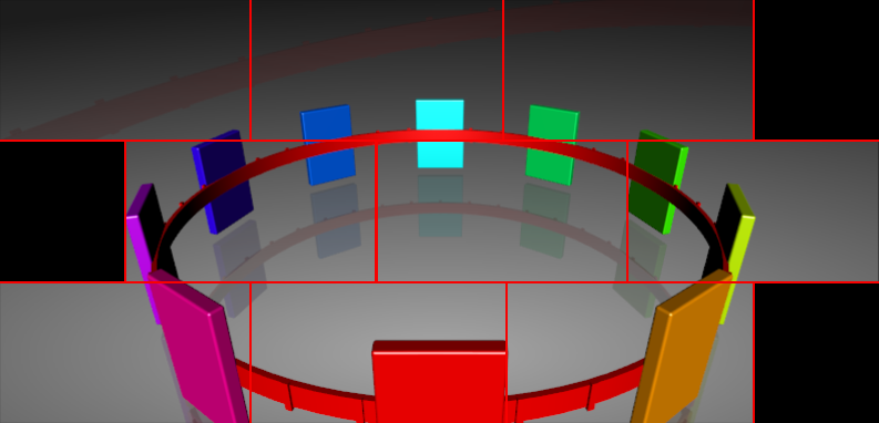
First, create a scene that just contains a Scene Port and save it. Add it to the project layouts in the Project Properties and activate the Direct3D Override to change the output resolution to 6720 x 3240 (three and a half times the display width by three times the display height). This way the complete scene can be viewed at once. In the screenshot below,a Render Target, Viewports and Overlay Rectangles have been used to simulate the placement of the displays in the real world. However, this step is of course optional.
The new layout can be now activated in the Stage Editor to see the whole scene on a single machine.
Production Layout
Add another Layout and call it Production. Activate the Direct3D Override and set the output resolution to 5760 x 1080, the region a single machine will render in Span Mode to fill its three displays. The first step is to adjust the aspect ratio to the resolution of the real world scene. This is done by inserting a Projection Node of the same type as used in the Design Layout before the Scene Port of the Production Layout. If there is no projection in the scene, Ventuz will use the default projection which type and value can be found in the Projection Node Documentation.
The next step is to insert a Matrix Scaling Operation between the Projection Node and the Matrix Node in the Content Editor. Since each machine will render one third of the height of the scene, set the Y-scaling to three. For the X-scaling, we divide the virtual width of our scene by the render output width (so 3.5 times display width divided by 3 times display width equals 1.166667).
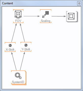
Finally, we need to shift the region of the scene the projection cuts out, dependent on the individual machine. This is done by using the ID property of a System ID Node with two Float Expressions which are then bound to the Center properties of the projection. For Y, we need to move one size of the output up or down for the first and last machine respectively. So
(2 - A) * 100
will calculate the correct percentage. For X, the first and last machine need to move the output to the left by a quarter of a display width and the middle machine has to move it to the right by the same amount to create the desired offset of half a display length.
((A == 2) ? 25.0f : -25.0f) / 3.0f
To verify the result, use the ID drop down box in the Stage Editor to simulate the different machines.