How To Render on a Machine Cluster
Table of Contents
Introduction
For a large Ventuz Scene that spans across multiple screens and computers, Clustering enables perfect rendering and playback.
If a setup requires more than one machine and more than one Ventuz Runtime, synchronizing animation and video playback becomes a problem. It is possible to a protocol such as OpenSoundControl (OSC) to start the animations/videos at the same time, but since all PCs are running on different unsynchronized time-bases, the animations and videos will drift and get out of sync. To avoid this, Ventuz provides the possibility of using a Cluster Clock, which ensures that all machines connected to the same cluster are receiving identical timing.
This page will describe the necessary technical steps to create a compelling multi-display / multi-projectors Ventuz presentation with a cluster of machines.
Building a Display Wall
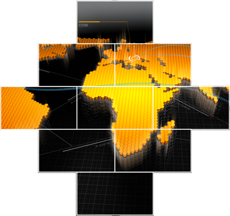
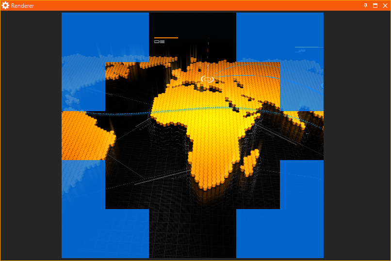
The goal of this section is to setup a cluster wall of nine 1920px x 1080px displays arranged as a rhombus. The cluster should consist of three machines with three outputs each. For this example we will assume that the displays are bezel-less. Each display has a resolution of 1920 x 1080. The final wall with Ventuz content on it could look like this:
The Visual and Logical Resolution per machine is limited to 16384 x 16384!
Creating a Render Setup
An appropriate Render Setup will need to be configured. Open the Ventuz Configuration Editor and select the participating machines by selecting their common group in the drop down in the top-right corner of the Configuration Editor.
If the machines for the cluster are already available in the network, it is important that they use the same non-zero Group ID and each machine has an ID starting from 0 for the first machine, 1 for the second, etc.
Ensure that each machine participating in the Cluster has the same Ventuz Presentation loaded into the appropriate project folder.
This can be achieved easily by Uploading a Ventuz Presentation using the dialogue in the Project Management tab. Click Upload in the top right corner and upload the appropriate VPR file.
While it is possible to configure the graphics driver to treat multiple outputs as one logical output, it is not necessary since Ventuz 7.
NVIDIA calls this Mosaic technology, AMD calls it Eyefinity. If this kind of setup is desired, configure the graphics card settings directly on the machines that need it using the appropriate graphics card software. These settings cannot be changed by Ventuz.
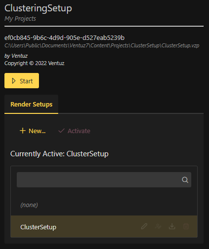
After the physical outputs have been configured, inside of the graphic card's software. Click on the Presentation File (VPR) that was uploaded in the first step of this section. In the panel on the right, click + New.... Choose a name and click OK. In this example, "ClusterSetup" is used. Clicking OK will automatically open the Render Setup Editor.
Layout
It is possible to accomplish this setup with or without any other computers connected to create a multi-machine (Cluster) Render Setup.
In the left menu, select Default Screen and then click Delete Selected Screen(s). This screen is not needed for this setup.
click on Add Screen(s), choose a name for the setup, in this case Rhombus Screen is used. Leave the resolution and advanced settings as default. In the Grid section of this pop-up, change the value from 1 x 1 to 3 x 3; This will create 9 screens in a grid.
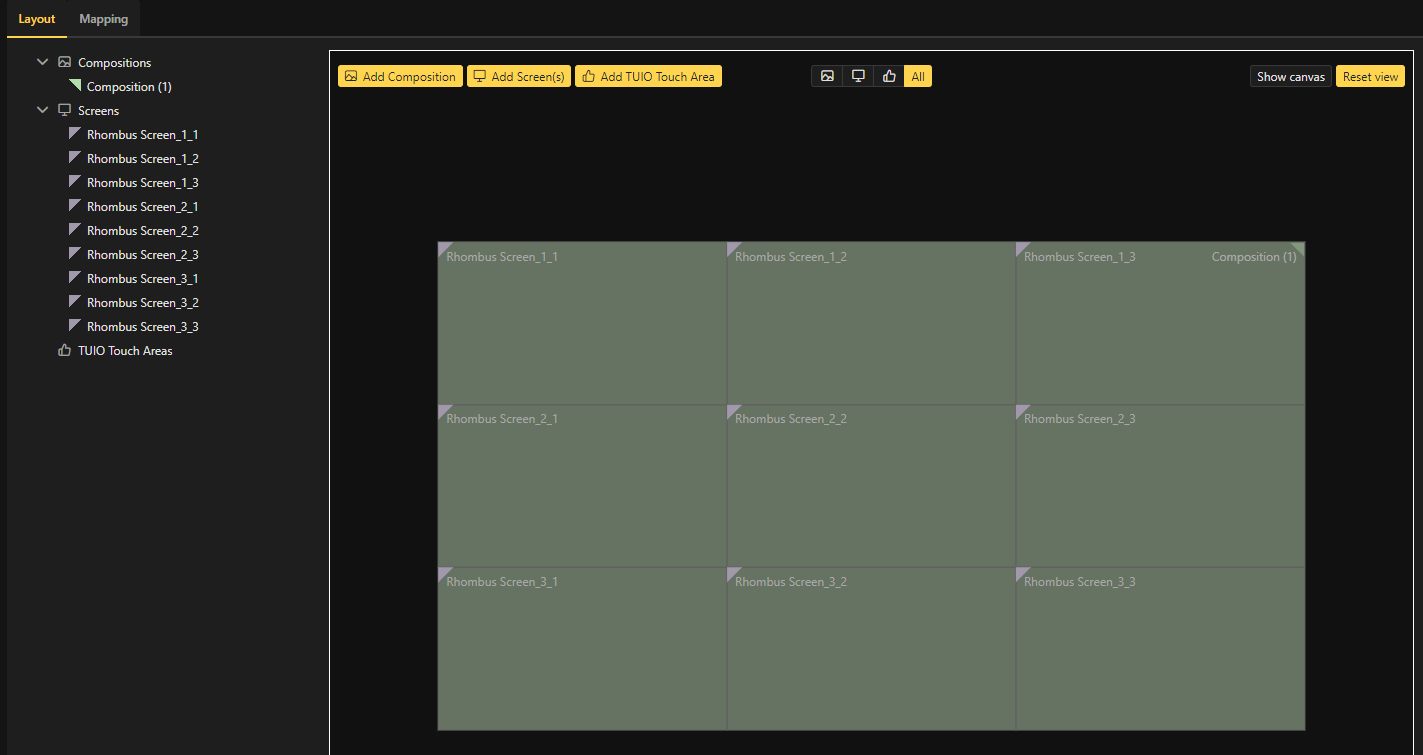
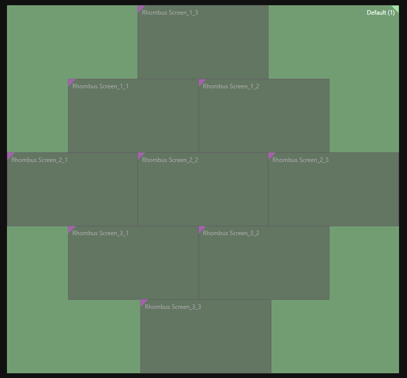
Drag each screen to achieve the desired Rhombus shape.
For more information on Layout Editing, see here
Mapping
Click on Mapping in the top left of the Render Setup window.
Delete the first Machine. Click on the Red Garbage Can. This will help in utilizing the built in Wizard to create and assign Screens to Outputs.
Click on the + Add Machine(s) button.
In the pop-up, add three machines by typing in "1 x 3" in the Machines text boxes.
Change the Outputs Per Machine the "1 x 3"
In the bottom drop-down menu, select the first screen in the setup: Rhombus_1_1
Click Add.
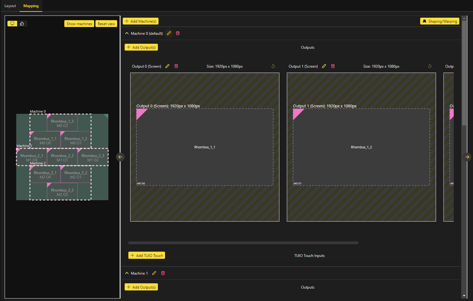
This Wizard has now created 3 Machines. Each Machine has an ID from 0 to 2. Each Screen from the Layout Setup has been assigned to an Output on each Machine.
For more information on Mapping Editing, see here
Save the new Render Setup and activate it as the active configuration for this Project in the Ventuz Configuration Editor. Every time this Project is loaded when Ventuz starts, it will automatically use this configuration for rendering. Depending on the ID of the machine, Ventuz will ensure the correct part of the Canvas will be rendered on each machine and to each output. The ID 0 will render the Cluster Preview. The Machine ID can be adjusted on-the-fly via Live Options or through the Ventuz Configuration Editor inside of the Configuration menu.
Changing and saving the active Render Setup configuration on a Machine while running Ventuz will instantly change the render output! Modifying the Render Setup will interrupt rendering in each Runtime!
Working with Render Setups in Ventuz Designer
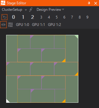
The way this new configuration will appear inside of the Renderer window in Ventuz Designer will appear as below. Ventuz renders rectangular areas and automatically applies a mask in the preview modes (Cluster and Machine Preview) to mark the rendered areas. The areas not masked represent the final rendered content in Production Mode when running in Ventuz Runtime.
Render Setup Modes
There are different rendering modes for Render Setup rendering available from the Stage Editor:
- Canvas Preview: This is a simulation of the whole Cluster with any number of machines and displays. Areas which will not be visible on the physical wall can be masked with a customizable color and alpha value. These values can be set in the Global Video Configuration or in the Live Options if Ventuz is already running.
- Output Preview: This mode allows the preview of each physical output of each machine that is in, or will be in the setup. Each machine can be selected by clicking on the numbers at the top of the Stage Editor. Each number selects displays the machine with that ID.
- Screen Preview: This mode displays what each screen is assigned.
- Design Preview: This preview mode is a shows the Ventuz Designer preview. Areas that aren't visible on a physical screen will be masked.
The last two modes are useful for checking whether or not a scene is well prepared for multi-machine, or cluster, rendering. The rendering mode can be changed in the Stage Editor by clicking on the display arrangement preview at the bottom of the Stage Editor. Click on a single highlighted machine or the border of the whole cluster to switch between Machine and Cluster Preview.
To get an aspect-correct rendering you will need to get into the Design Preview. But beware if "preview without scaling" is not enabled then this is just a estimation done by Ventuz. To give you a idear on how it will look like. Enabling "preview without scaling" will ensure to display the correct aspect ratio. Just note that on bigger and more demanding scenes this can cause your performance to drop inside the Designer.
Layer EffectsMGPU: , Cluster:
There are some considerations to be bade when using Layer Effects in a Clustering Render Setup. Because the machines do not render the whole scene, any effects that need to consider multiple pixels at once may not work out of the box. "May not work" means that the effect will not look correct across or close to machine borders.
For example, effects such as blur calculate its effect based on the surrounding pixels. When Clustering, some of the pixels close or on the edge of the Cluster will not be calculated on a different part of the Cluster.
To fix this issue, the Effect Bleed can be changed in the Device Configuration of the Ventuz Configuration Editor. The Effect Bleed property is set globally for all video outputs and can be found in the Global section of the Video tab in the Device Configuration. This option expands the rendered texture of the machine by the set value. The value is set in percent of the output height, which is then applied to all four edges. Although the added area is not visible on the physical output, it can be calculated by said effects and can produce correct results again.
Some effects need to consider the whole screen so they can calculate which pixels need to be taken into account ahead of time. These effects should not be used in a Cluster Setup as it would negate the advantage of using multiple machines; which is better performance through splitting the image in multiple parts each rendered by only one of the machines.
Multitouch and InteractionMGPU: , Cluster:
Under some circumstances, all Interaction Nodes will work without issue in a Multi-Machine setup. There are some conditions which must be fulfilled:
- The BehaviorApply property on all Touch Transformation nodes has to be disabled. If this option is enabled, a physical simulation (like Inertia) is calculated within the nodes and applied to the transformed geometry; This simulation is not synchronized over all machines within a Cluster and will result in different values per machine and can produce different undesired render results.
- In the Project Settings in the Interaction category Smoothing Weight and Interpolation Delay must be set to 0.0! Because touch data packets may not arrive simultaneously from the packet's source, smoothing and interpolation will create issues because the processing is based on time difference of received packets.
- The Cluster must be symmetrical. This means that every machine in the Cluster must have the same resolution. E.g. 4x3 displays should be fed by 3 machines with a 4x1 screen setup. A screen setup like 2x2 + 2x2 + 4x1 is not recommended as the touch calculations are dependent on the resolution of the renderer. Different resolutions can lead to (slightly) different touch transformation results.
- A Master-Client setup should be preferred over an All-Single setup for the Cluster touch network settings (see Cluster Interaction Settings). In the Master-Client setup the interaction inputs are only received by the Master machine and distributed to the Clients through a Ventuz-internal protocol.
A Master-Client touch setup for a multi-machine Cluster requires a GroupID > 0 on the involved machines!
All machines of the same Cluster need to receive the same input signals such as TUIO. The coordinate space of the input must be mapped to the Cluster coordinate space: top-left corner of the Cluster bounding-box would be [0;0] and bottom-right would be [1;1]. Every machine takes the input signal and transforms it into its local coordinate space. Note that a Cluster display-wall built up of Windows Touch screens will currently not interpret the touch inputs correctly.
The Web Browser node can also be used on a multi-machine wall to create one huge browser. There are also some limitations which must be considered:
- Every Web Browser node renders the whole web page even if most parts of the page are not visible on a machine.
- Browser page size is currently limited to 4096 x 4096 pixel. Thus a Cluster with a higher resolution will display a scaled up web page.
- Loading and presenting the web content is not synchronized over the machines as the content is rendered discreetly in each browser (client).
Math Effects
Under some conditions, some of the Math Effects Nodes may cause issues. Some environments have machines that do not render simultaneously. For example, the Modulo operation on one machine may have reached the boundary value while another machine is 1 or 2 frames behind having not reached the value. This may cause serious problems depending on the setup of a scene. Please note that this is not a major issue when it comes to cluster rendering. But keep in mind that issues like this may occur and should be considered if unexpected behaviour appears in a scene even though the logic is faultless.
Setting up the Hardware
Following recent Microsoft Windows Updates to Full Screen Optimization, synchronization between frames across multiple GPU outputs may not be as predictable as before.
Enabling Mosaic Mode can solve this issue. In most cases, the timing discrepancies are minimal and unlikely to be noticeable to users. However, in scenarios where multiple displays are arranged with adjacent pixels, such as two touching LED walls using two outputs, such discrepancies may become more apparent. To ensure optimal synchronization in these situations, we recommend enabling Mosaic Mode. This only occurs when using multiple outputs on one GPU. If only one output is being used, this issue does not occur even if using multiple GPUs in one machine.
Make sure that every machine participating in a Cluster has the same Ventuz Version installed and that the Ventuz Machine Service is running.
A Ventuz Cluster setup will only work correctly in Ventuz Runtime. If running from inside Ventuz Designer, delays, artifacts, and synchronization issues can occur. Thus ensure that all presentations and shows are run from within Ventuz Runtime, not Ventuz Designer!
Cluster Clock and Cluster ID
In order to set up a synchronized Cluster environment, a Cluster Feature license is needed. Setting the Group ID in the Ventuz Configuration Editor to a value greater 0 will automatically enable the Cluster Clock synchronization via the network.
Make sure that all machines that are using the same cluster clock have the same Group ID; This ID must be greater than zero! Each machine needs a different Machine ID applied. The machine with the lowest Machine ID within a group will serve as the Cluster Clock Master. The algorithm used for interchanging the cluster clock information is easy and transparent: Every machine sends out its current time after it has finished rendering a frame but before the vertical retrace of the graphics card has occurred. As soon the vertical retrace releases the renderer from its wait state, every machine receives all clock information from all other machines - including its own. Every machine simply selects the clock from the lowest Machine ID it has received and adds a value of one to enter the next rendering cycle. This makes the lowest ID the Master but if the master stops rendering or has been disconnected from the network the next machine will become the Master on-the-fly!
For synchronized Clusters in DirectX Output mode it is important to set the Prevent D3D Queuing to ON in the Device Configuration!
To achieve the optimum Cluster Clock it is crucial that:
- All machines have identical hardware.
- The same scene on all machines is bing used (use the SystemID node to apply machine specific settings)
- The scene is running properly with the maximum frame-rate.
- Identical project and graphics card settings are used (a different anti-aliasing setting will bring the clock out of sync).
- Disable Bezel or Overlap settings in the graphics card as this feature is achieved by the Render Setup rendering in Ventuz.
- All machines are connected to the same network.
Once the cluster is set up properly, all timing related nodes are affected by the Cluster timing. Some nodes, like Scroll Text, Counter or Ticker can be configured to work either frame based or time based. In order to synchronize those nodes via the Cluster Clock the Progress property has to be set to time based.
When activating the statistics in the render window, there is some additional information:
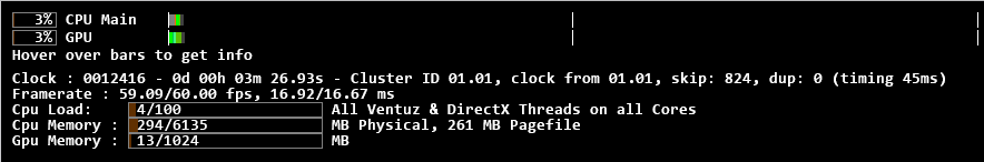
Cluster ID 01.02 means that this machine has the Group-ID 01 and the Machine-ID 02, the following number shows the current value of the cluster clock, and the clock from 01.01 indicates that the current clock master has Machine-ID 01. On a client system, the type of the cluster clock is colored GREEN, on a master system it is BLUE.
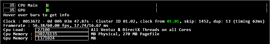
A font color change on a client system from green to white indicates that the client has lost its master clock and is running independently. Make sure that the client systems show constant green writing without any flickering between green and white.
There is one unique feature for Nvidia in synchronized cluster setups. When using a Nvidia framelock setup with enabled Swap Sync, it is possible to get the timing for the Cluster Clock from the synchronization board. As this is not based on a network protocol, this is method is more precise. In this case the digits that represent the clock master in the statistics show FL (Framelock). Read more about synchronizing a cluster below.
Movers in Absolute mode are always running in sync no matter when the scene was started. Nodes that need to be triggered (e.g. Mover in OneShot mode) must receive the trigger signal simultaneously. This can be achieved by using e.g. OSC multicasting.
Remoting
As soon as multiple Ventuz machines are running in a Cluster the Remoting Interface can be used to synchronize execution of commands on all related machines.
Network multicast cluster setup
Every PC in the Ventuz Cluster broadcasts the Cluster Clock every sixtieth of a second to the network; consequently, a substantial amount of network traffic may be present. The Cluster Clock should run on a network on a dedicated switch (or hub).
Multicast messaging with multiple network interface cards
The Cluster must be set up on the network card (NIC) that is connected to the Cluster Clock network to the lowest metric. Use the route command in the CMD Shell. Run the CMD shell as Administrator (right click "cmd prompt", choose Run as Administrator).
route change 224.0.0.0 mask 240.0.0.0 <IP of network card here> metric 25
To make this persist then add -p, otherwise changes will be lost with the next reboot.
Synchronization Hardware
In a cluster environment synchronizing the outputs needs to be considered, especially in the case of video playback, having any frames of delay between outputs may be produce undesirable results. For those scenarios, additional hardware is required - sync boards can be used. Popular examples are the AMD FirePro S400 Synchronization Board and the NVIDIA Quadro G-Sync Boards. Some information about different synchronization scenarios can be found on the Cluster page.
Setup
To synchronise the Cluster's outputs, install a synchronization board in every machine in the cluster, following the manufacturers instructions.
Every sync board has one BNC connector for an external timing source and two RJ-45 connectors to connect the sync boards to each other. Be aware that the RJ-45 are only for connection between the sync boards. Do not connect them to a usual Ethernet port or network switch as this can cause damage to the boards. As in the image below, the connection between the sync board is independent from the Ethernet connection.
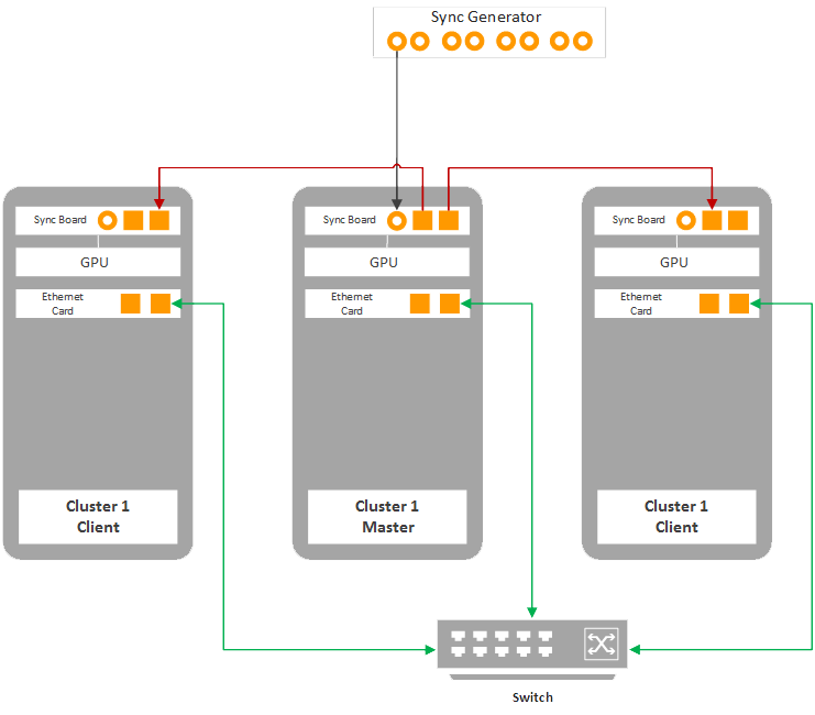
To synchronize the cluster, one machine acts as the timing server, the others as clients. For Framelock applications, the timing server uses an internal signal as timing source. For Genlock applications, connect an external timing source, e.g. the 'house sync', to the timing server via the BNC connector as seen in the image above.
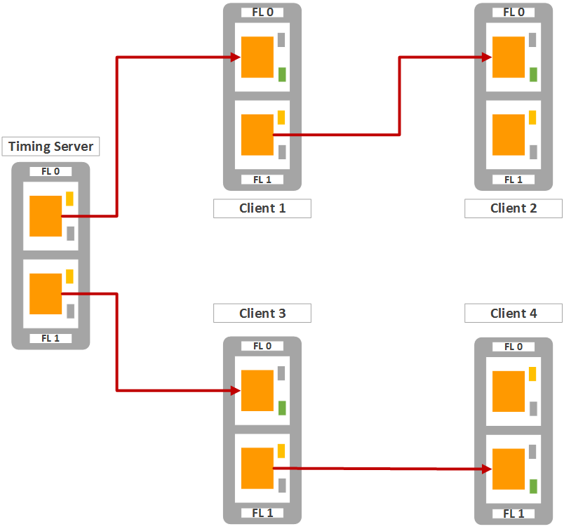
The machine that acts as the timing server uses both of its RJ-45 as outputs to distribute the timing signal. A client uses one as input and the other one as output, so the signal can be passed to another client. It is recommended to split the clients in two equal groups and arrange each group as a daisy chain connected to one of the two timing server outputs.
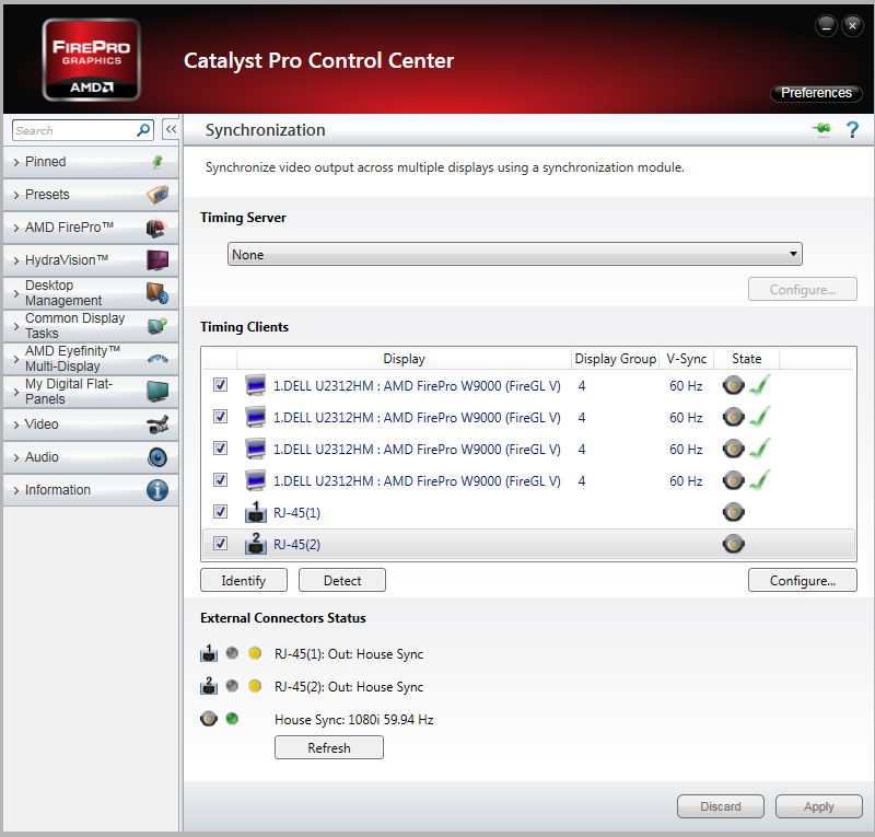
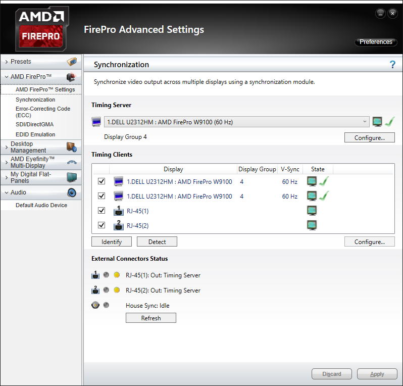
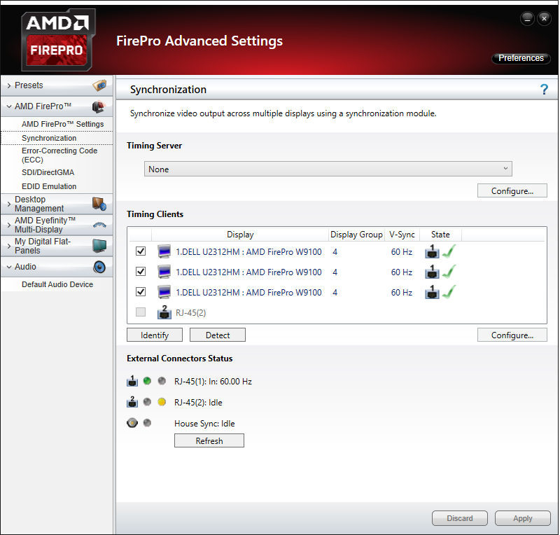
Next, configure the timing master and client in the graphics card driver. See the graphics card manual for details. Below is an example screenshot for a four display machine set up as timing master. Configured in AMD Catalyst Control Center. The timing signal comes from an external sync generator.
Here an example to synchronize two machines where the left machine is the timing master. This configuration is crucial to use Swap Sync in Ventuz!
 | 
|
For detailed information on how to set up the synchronization boards, refer to the manufacturers documentation.
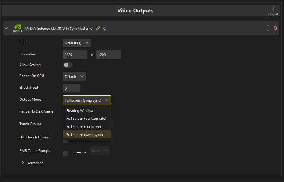
Enable Swap Sync
Now that the displays' refresh rates are set to a common time source, internal or external, tearing or flickering should be prevented. This was done in the graphics card configuration. As described above, Swap Sync requires support by the application - Ventuz in this case. To enable swap sync, move to the DirectX Output of the Device Configuration.
Be aware that Swap Sync only makes sense and only works if the synchronization boards are configured correctly.
Note that Swap Sync only works in exclusive fullscreen mode!
Our experiences with AMD Boards
- AMD suggests to boot the timing master first, then the clients in the order they are connected to the master. This way the timing signal is present when the client comes to live. Shut down vice versa.
- AMD boards loose their configuration almost every time they loose the timing signal. AMD's recomendation is to ensure the have boards configured correctly using presets in the Catalyst Control Center and load these after every startup. This can be found in in the Catalyst Control Center help.
Our experiences with Nvidia Boards
- For stable results, Nvidia suggests to boot the clients first, then the master.
- Nvidia boards remember their configuration, even if they loose the timing signal, which makes reconnecting easy.
- For Swap Sync to work properly, only one logical display can be connected to the Nvidia GPU.
- Mosaic mode provides only one logical display, so this works fine.
- All monitors connected to additional Nvidia GPU's must be part of the mosaic.
- It is OK to have an additional Nvidia GPU with no monitors connected
- It is OK to have an additional Amd / Intel GPU with monitors connected (which is very helpful for debugging)
- If one machine stalls for a longer period of time (>~5s), the other machines in the cluster will have an issue. The graphics driver will stall and causes a Windows timeout restarting the graphics driver and crashing Ventuz. Timeout Detection & Recovery. This may be avoided by the following Registry Key entry.
    // disable Timeout Detection & Recovery
    KeyPath   : HKEY_LOCAL_MACHINE\System\CurrentControlSet\Control\GraphicsDrivers
    KeyValue  : TdrLevel
    ValueType : REG_DWORD
    ValueData : 0
Check List
Unfortunately, every use case can not be considered in setting up a cluster. The following is a list of some methods to avoid issues when setting up:
- All machines have exactly the same display driver version.
- An appropriate group ID (>0) and machine ID has been assigned to each machine.
- If the way displays are connected has changed, reboot all systems.
- If a firewall is used, make sure it does not block the cluster clock address/port (225.225.225.1:19300)
- Do not use consumer grade graphics cards. They cause problems are difficult to diagnose.
- Run the presentation in Ventuz Presenter, not in Ventuz Designer.
- The presentation must run in a fullscreen output mode See: Video Device Configuration.
- The cluster clock values in the Performance Statistics are rendered in green and do not flicker to gray (without Genlock/Framelock it is, in general, not possible to avoid this).
- Ensure the framelock settings in the graphics card driver are correct before starting Ventuz.
- If Swap Sync should be used this must be enabled in the Device Config of ALL machines!
- When running in Ventuz Designer is unavoidable (which is advised against), make sure the FPS in the Device Configuration is set consistently. Otherwise animations will run at different speeds.
- As a primary test for a correct setup run the 'Default.vpr' (build-in presentation) on the Cluster. If this very simple scene does not run synchronously, the cluster setup is incorrect. Ensure that the conditions above are fulfilled!
- the final scene should run smoothly with full framerate on each machine (without cluster synchronization). Many (long) frame-drops disrupt the Cluster synchronization!
When changing the number of displays attached to the graphics card or their cabling, reboot the machine. Hot-Swapping displays is not recommended.
Limitations
Multi Touch and Interaction
Windows Touch is does not work in a Cluster! Use TUIO for touch.
Keyboard nodes work inside a cluster configuration.
Layer Effects
Following is a list of all Effects with hints to use the Effect Bleed or if should not use them in a cluster at all.
| Effect | Cluster Compatibility | |
|---|---|---|
| Grayscale Color Grading Color Correction Gain Posterize RGB Posterize HSV Color Difference RGB Noise Delay all Masks |  | works in cluster without problems |
| Mosaic Blur Glare Dropshadow Edge Detection Lens Distortion Distortion RGB Distortion 2D Displacement Noise Distortion |  | works with Effect Bleed only |
| Feedback | | often fails in cluster with an Effect Bleed - depending on parameters |
| Crashzoom Polar Distortion Kaleidoscope Distortion |  | does not work with an Effect Bleed |