Custom Effect Shader
Table of Contents
 | Custom 2D Effect | Adds a custom shader to layer effects. |
| Custom 3D Effect | Adds a custom shader to 3d layer root node, with access to camera information and depth buffer. |
 | Custom Effect Shader | Contains the actual custom shader that is added to layer effects or 3d layer root. |
The Custom Effect Shader allows you to write your own postprocessing effects for 2D and 3D layers using the HLSL shader language. This page describes the general usage and properties of the node and multiple shader techniques. In the F1 Help of the Custom Effect Shader node is also a set of shaders with different complexity.
A shader is written in an external text editor. Annotations in the shaders comments allow to bind shader constants / uniforms to be exposed as Ventuz properties. Other important information like viewport size is provided via special names for shader constants / uniforms.
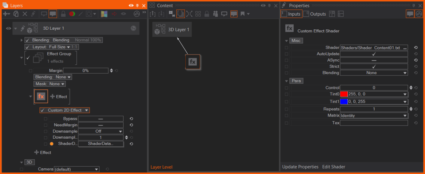
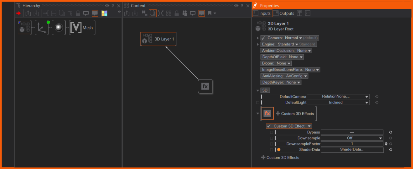
The custom effect can either be placed as 2D Effect in the layer's effects section or on root node of the layer. With selecting a default shader, the Custom Effect Shader node is automatically added and bound.
| 2D Custom Effect on Layer Effect section | 3D Custom Effect on Layer Root node |
|---|---|
 | 
|
The Nodes
A custom shader setup consists of three parts:
- The shader source as a text file. This is authored outside Ventuz using your favorite code editor.
- The Custom 2D / 3D Effect property group to place the shader in the layer system.
- a Custom Effect Shader node that loads the shader source and holds the shader constant / uniforms as bindable properties. This node binds to the Custom 2D / 3D Effect property group.
Custom 2D Effect
The Custom 2D Effect is part of the layer's FX section. It provides the shader the rendered 2D texture. On the shader's output, other effects can be applied, by adding them behind the Custom 2D Effect in the FX chain. The Custom 2D Effects needs the shader provided by a bound Custom Effect Shader node. The shader can access layer properties, like pixel count, as Special Names.
- Bypass: Bypasses the custom effect
- NeedEffectBleed: Enables the layer to render it's effect bleed .
- Downsample: The shader can be run with a lower resolution than the layer, to save performance. After the shader computation the shader texture is upsampled to match the layer. If Filtered is active, a bilinear filter is applied.
- Downsample Factor: Sets the factor of which the shader is downsampled to the layer. Recommended is to use powers of 2.
- Shader Data: Binds to the ShaderData output of the Custom Effect Shader. This is mandatory.
Custom 3D Effect
The Custom 3D Effect is placed on the 3D Layer's Root Node of a 3D Layer. It also needs to be bound to a Custom Effect Shader node. The 3D effect can access the camera information of the layer and the depth buffer, via Special Names. The properties of effect have the same functionality as the 2D effect.
Custom 2D Effect on a Layer Group
In general the effect works the same on the Layer Group, but it has access to up to four layers inside the group, with their texture and layer transform matrix.
Custom Effect Shader content node
The provider for the effects is a separate Custom Effect Shader content node with the ShaderData output.
Input properties:
- Shader: Loads the shader text file via the standard open dialog (...) or a provided URI. Edit the shader file via your favourite HLSL editor or any text editor.
- AutoUpdate: Auto-loads / updates changes of the file.
- ASync: Loads the shader asynchronous, if enabled.
- Strict: Sets the HLSL compiler to strict mode, if enabled.
- Blending: Defines how the shader is blended with the layer. None: Does not perform any blending, simply uses the output color buffer. Alpha: Uses the alpha channel of the output buffer to perform an alpha blend. Additive: Adds the shader output onto the layer rendering.
Outputs:
- ShaderData output: provides the data for the Custom Effect nodes on the layer
- Messages: If there are any errors they will be written to this output or a confirmation, that the compilation was successful.
- CompileOk: True when the shader compiles.
- Loaded: Shader loaded successfully.
- Failed: The shader failed. Check the message output or the Performance Statistics.
If an edit of the shader fails to compile, the current running shader will be hold in memory and stays running. The message output and the Performance Statistics output the error message of the failed shader. While working on a shader it is recommended to activate the Performance Statistics with CustomPostprocess selected.
- Update Properties: This function at the bottom of the Property Editor updates the input properties, if the shader code has changed and some inputs are not used anymore, they will be deleted.
The next section describes multiple shaders. It is recommended to read the whole section, to get an overview which specific Ventuz features and their usage are integrated.
Simple Shader
This is an example for a simple shader:
// constants / uniforms must be in a constant buffer

cbuffer Compute : register(b0)
{
    float3 Tint0;			//# color =0
    float3 Tint1;			//# color =1
}

// output and input texture

RWTexture2D<float4> _ColorOut;
Texture2D<float4> _Color;

// compute shader that tints every pixel

[numthreads(16,16,1)]
void main(in uint3 DispatchThreadID : SV_DispatchThreadID)
{
    uint2 pos = DispatchThreadID.xy;

    float4 color = _Color[pos];

    color.xyz = lerp(Tint0.xyz, Tint1.xyz, color.xyz);

    _ColorOut[pos].xyzw = color;
}
Tint0 and Tint1 are detected as shader constants / uniforms. The //# is a special comment that indicates how the input property of the node is formatted. In this case, a color input property with the default of (1, 1, 1) or (0, 0, 0) is generated.
_ColorOut and _Color are special names that connect to the output and input texture of the postprocessing effect.
As this will be run as a compute shader, a threadgroup size must be specified. A 16x16 kernel is a reasonable default. Only pixels within a kernel are accessible. Note that in compute shaders automatic LOD calculation is not available, so Texture.SampleLevel() or Texture.SampleGrad() must be used instead of Texture.Sample().
Shading Language Extensions
Custom effect shaders are written as DX11 Compute Shaders in HLSL using the cs_5_0 profile. Constants / Uniform shader variables must be placed in the first constant buffer and automatically create Ventuz properties. Expressions involving only constants / uniforms are not automatically moved outside the shader, they are calculated per pixel.
Annotation Syntax for Shader Constants / Uniforms
To customize the Ventuz properties, comments placed after the definition of a constant are parsed by Ventuz:
float One;        //# 0..1 step 0.002 = 1
float Positive;   //# 0.. step 0.125 = 1
float Negative;   //# ..0 step 0.125 = -1
float4 Color;     //# color = [0.5, 0.5 ,0.5, 1]
float3 Mixed;     //# 0..[1, 0.5, 1] step 0.125 = [0, 0.5, 0]
uint Enum;        //# enum a,b,c = 1;
Samplerstate sam; //# point clamp
Only constants which are used inside the main loop are displayed in the node properties!
Int and Float
Int and float annotations consist of 3 optional sections: range, step and default.
The range is specified in one of these ways:
- minValue..
- ..maxValue
- minValue..maxValue
The step is specified as:
- step value
The default is specified as:
- = value
Scalar values can be integers or floats. For vector variables, a value can be specified as a scalar, meaning that the same value is used for all vector elements, or a vector notation with square brackets:
- [1,2,3]
Enumerations
Enumerations annotation consists of the "enum" keyword, a comma separated list of values and an optional default:
uint test //# enum a,b,c = 0
As the cs_5_0 profile does not know about enums, enumeration variables are defined as unsigned int, and the enumeration values can not be used in the shader code, they must be entered as integers starting from 0. The same goes for the default value, which is also an integer.
The enumeration values will only be used for the user interface of the property group to make using the shader easier.
Colors
Color annotation consists of the "color" keyword and an optional default:
float3 color //# color = [0.2,0.4,0.6]
This will create a color picker user interface.
Colors must be of type float3. If you need an alpha channel, add another float variable.
Textures
Textures do not need any annotation.
Samplers
Samplers do not create any properties. You must describe the sampler in the shader source, and it can not be changed.
You can specify filtering and addressing:
For filtering, one of:
- "point"
- "trilinear" (default)
For addressing, one of:
- "clamp"
- "wrap"
- "mirror"
- "border black" : rgba = float4(0,0,0,1)
- "border white" : rgba = float4(1,1,1,1)
- "border transparent" : rgba = float4(0,0,0,0)
SamplerState sam; //# point clamp
Matrices
The following matrix types are supported. No annotation is needed to create a matrix property:
- row_major float3x4
- column_major float4x3
- float4x4 (any order)
Special Names
Some names get information from the Ventuz runtime and do not generate properties:
- uint2 _ScreenSize : target size in pixel
- float2 _InvScreenSize : one over target size
Only available in custom 3D effects:
- float4x4 _cs2ss : matrix from camera space to clip space (projection)
- float4x3 _ws2cs : matrix from world space to camera space (view)
- float4x4 _ws2ss : matrix from world space to clip space (view*projection)
- float4x4 _ss2cs : matrix from clip space to camera space (inverted projection)
- float4x3 _cs2ws : matrix from camera space to world space (inverted view)
- float4x4 _ss2ws : matrix from clip space to world space (projection-1 * view-1)
- float4x3 _RayMatrix : matrix used for raymarching
Special Textures / UAVs:
- RWTexture2D<float4> _ColorOut : UAV texture that holds the target
- Texture2D<float4> _Color : Texture that holds the input
Special textures in Group Layers:
- Texture2D<float4> _Layer0 : First layers texture
- Texture2D<float4> _Layer1 : Second layers texture
- Texture2D<float4> _Layer2 : Third layers texture
- Texture2D<float4> _Layer3 : Fourth layers texture
- bool __LayerX_Enable : In a group layer, this layer is visible, not blocked directly, and not blocked by alpha/opacity. Note : 2 underscores
- float __LayerX_Opacity : In a group layer, opacity of the layer, 1.0 for 100%. Note : 2 underscores
- float3x2 __LayerX_Matrix: In a group layer, transformation matrix of layer (aka the layer layout) Note : 2 underscores
- float3x2 __LayerX_InvMatrix : In a group layer, inverted transformation matrix. Note : 2 underscores
Special textures that are only available in custom 3D effects:
- Texture2D<float> _Depth : Texture that holds the depth
Each normal texture creates a set of special names with information about the texture. XXX is replaced by the name of the texture:
- uint2 _XXX_Size : size of texture in pixels
- float2 _XXX_InvSize : one over size of texture
How To
Using Texture Properties
When you define a texture like this:
Texture2D<float4> MyTex;
SamplerState MySam;           //# trilinear clamp
The normal way to put this texture full-size on the screen is:
uint2 pos = DispatchThreadID.xy;                            // get pixel coordinate
float2 fpos = float2(pos) * _InvScreenSize;                 // transform to 0..1 range

float4 tex = MyTex.SampleLevel(MySam, fpos, 0);             // sample pixel
- You can use the same sampler with multiple textures, as long as the settings for the sampler are the same
- As we are running in a compute shader, you need to use the SampleLevel() function.
- The variable _MyTex_Size and _MyTex_InvSize are supplied for MyTex should you need them.
You can also access textures without sampler using indexing: MyTex[pixelpos]. One could place the texture on screen without filtering like this:
uint2 pos = DispatchThreadID.xy;                            // get pixel coordinate
float2 fpos = float2(pos) * _InvScreenSize;                 // transform to 0..1 range

float tex = MyTex[uint2(fpos * _MyTex_Size)];               // load pixel
This is most useful for the provided _Color, _ColorOut and _Depth as they need no filtering in most cases.
The shader is limited to 4 input textures (including _Color) after optimization and compilation.
Using Matrices
Matrices are passed in transposed form:
| sx 0  0  tx |
| 0  sy 0  ty |
| 0  0  sz tz |
| 0  0  0  1  |
This allows to pack an affine matrix as a 4x3 matrix in 48 bytes, by just omitting the final "0 0 0 1".
You can create matrix properties, or inside a 3D effect, use the predefined matrices which are synchronized with the current camera:
- float4x4 _cs2ss : matrix from camera space to clip space (projection)
- float4x3 _ws2cs : matrix from world space to camera space (view)
- float4x4 _ws2ss : matrix from world space to clip space(view*projection)
Spaces
Most matrices are used to transform vectors from one "space" to another. It is good practice to label all vectors with ws, cs, or ss to clarify the space they are in.
- ws world space : The world coordinate system
- cs camera space : Position as seen from the camera
- ss clip space : homogenous xyzw coordinate
- ds normalized device coordinates : x and y in -1..1 range, and depth in the 0..1 range from clip near to clip far.
To get from clip space to normalized device coordinates, divide xyz by w. This is used to correctly test against the depth buffer.
float3 csPos = fromsomewhere();
float4 ssPos = mul(_cs2ss, float4(csPos,1));
float3 dsPos = ssPos.xyz / ssPos.w;
'ss' is a bit of a misnomer, it used to mean "screen space", but that's not correct, and the 'cs' was already used, so just keep it. We could use the term "eye space" which is equivalent to "camera space", but this is historic, changing it would be a mess.
Row or Column Major
We prefer row-major matrices, where the matrix comes as first argument when multiplying (operator-style)
row_major float4x4 _cs2ss;
row_major float3x4 _ws2cs;

// ..

float3 csPos  = mul(_ws2cs, float4(wsPos ,1));
float3 csNorm = mul(_ws2cs, float4(wsNorm,0));
float4 ssPos  = mul(_cs2ss, float4(csPos ,1));
Alternatively, using the column_major default, which puts the matrix as second argument in the multiplication:
float4x4 _cs2ss;
float4x3 _ws2cs;

// ..

float3 csPos  = mul(float4(wsPos ,1), _ws2cs);
float3 csNorm = mul(float4(wsNorm,1), _ws2cs);
float4 ssPos  = mul(float4(csPos ,1), _cs2ss);
The memory layout for both cases is the same, so both works from the same constant buffer. The matrix is just interpreted differently.
Color Spaces
For correct colors, the shader must operate in the project color space.
To convert inputs into this color space, functions and configuration macros are provided. These functions are included automatically to the source.
- The special _Color and _ColorOut textures are always in project color space, so usually no need for conversion.
- Texture properties that come from a texture loader property are in whatever color space the image file is and should be converted to project color space.
- The special name _LayerX textures will be in project color space when they come from a Group or 3D Layer, or be in whatever color space the image is for an image layer.
So all input textures except the _Color texture should go through a color space handling function.
To do so, the CSC() function is provided that takes many parameters. As color space operations may change in future versions of Ventuz, one should not specify these parameters manually, but use the a macro that is provided for each input texture. The macro syntax is: TEX_TextureName or for a layer TEX__LayerX with double ''.
For a texture like MyTex, the color space conversion code looks like this:
float4 mytex = CSC(TEX_MyTex, MyTex[pos]);
The special-name _Color never requires color space conversion, but if you accidentally implement it, this will work as a no-operation.
float4 layer0 = CSC(TEX__Layer0, _Layer0[pos]);
float4 color = CSC(TEX__Color, _Color[pos]);
Here is a full example that mixes foreground from texture with background, doing color space conversions correctly.
cbuffer Compute : register(b0)
{
    float2 _InvScreenSize;
}

RWTexture2D<float4> _ColorOut;
Texture2D<float4> _Color;

Texture2D<float4> Tex0;
SamplerState sam;                                    //# trilinear border transparent

[numthreads(16,16,1)]
void main(in uint3 DispatchThreadID : SV_DispatchThreadID)
{
    uint2 pos = DispatchThreadID.xy;
    float2 fpos = float2(pos) * _InvScreenSize;

    float f = saturate((length(fpos*2-1)*0.75-0.5)*100+0.5);       // calcualte a mix-factor

    float4 t0 = _Color[pos];                                       // no csc for background required
    float4 t1 = CSC(TEX_Tex0,Tex0.SampleLevel(sam, fpos, 0 ));     // csc for texture

    _ColorOut[pos].xyzw = lerp(t0, t1, f);                         // no csc for output
}
Layer Group Shader
In a Group Layer, the first four layers can be accessed.
The shader will be called in the normal way, meaning the special name texture _Color contains the image as the group normally blends it's input layers on top of a background. For the sub-layers the blending property is not taken into account when accessed directly, only for the group blend.
If you want to blend directly on the unmodified background, one can set all layers inside the group to 0% opacity and disable BlockOnFullTransparency. This will keep rendering the layer but not blend it over the background, so the shader can implement custom blending on top of the unmodified background. With the Special Names float __Layer1_Opacity the opacity of the layer or with bool __Layer1_Enable the visible flag can be used for custom blending.
The layer inside the group may transformed through the layout property. This transformation must be applied manually with a matrix that is provided. This is important to not access black pixels from a transformed layer.
cbuffer Compute : register(b0)
{
    uint2 _ScreenSize;
    float2 _InvScreenSize;
    float offset;                   //# step 0.01 = 0;
    float size;                     //# 0..1000 = 10;

    float3x2 __Layer0_Matrix;       // special name for first layer transformation
    float3x2 __Layer1_Matrix;       // special name for second layer transformation
}

RWTexture2D<float4> _ColorOut;
Texture2D<float4> _Color;

Texture2D<float4> _Layer0;			//Texture of first layer in group
Texture2D<float4> _Layer1;			//Texture of second layer in group

SamplerState sam;                   //# point border transparent

[numthreads(16,16,1)]
void main(in uint3 DispatchThreadID : SV_DispatchThreadID)
{
    uint2 pos = DispatchThreadID.xy;
    float3 fpos = float3(float2(pos) * _InvScreenSize, 1);

    uint select = uint((float(pos.x+pos.y)) / size + offset) % 3;

    float4 color = _Color[pos];

//samples Layer0/1 with pre-multiplied matrix to always access on the actual layer content and not "next to it" by accident
//for Layer1 a color conversion is applied, which is necessary if the layer is a texture layer

    if(select==0) color = _Layer0.SampleLevel(sam, mul(fpos, __Layer0_Matrix), 0 );
    if(select==1) color = CSC(TEX__Layer1, _Layer1.SampleLevel(sam, mul(fpos, __Layer1_Matrix), 0 ));

    _ColorOut[pos].xyzw = color;
}
Depth Buffer Access and World Space Reconstruction
Custom 3D effects have access to the depth buffer.
This code shows the depth buffer. To see it more clearly, you should set the far clipping plane to something really close.
cbuffer Compute : register(b0)
{
    float2 _InvScreenSize;
    row_major float4x4 _cs2ss;
    row_major float4x4 _ss2cs;
    row_major float3x4 _cs2ws;
}

RWTexture2D<float4> _ColorOut: register(u0);
Texture2D<float4> _Color: register(t0);
Texture2DMS<float> _Depth: register(t1);

void main(in uint3 DispatchThreadID : SV_DispatchThreadID)
{
    uint2 pos = DispatchThreadID.xy;
    float2 uv = pos * _InvScreenSize;
    float4 color = _Color[pos];
    float depthSs = _Depth[pos];

    _ColorOut[pos].xyzw = float4(depthSs.xxx,1);
}
The depth value is in clip space, which goes from 0.0 for the near clipping plane to 1.0 for the far clipping plane. To convert this to Ventuz units we can use the camera space to clip space matrix (cs2ss) :
float depthCs = _cs2ss._34 / (depthSs * _cs2ss._43 - _cs2ss._33);
We can even reconstruct the world space position, this uses the inverted matrices:
    float4 posSs = float4(uv.x*2-1, 1-uv.y*2, depthSs, 1);  // clip space position
    float4 posCsH = mul(_ss2cs, posSs);                     // camera space as homogenious coordinate
    float3 posCs = posCsH.xyz / posCsH.w;                   // perspective divide
    float3 posWs = mul(_cs2ws, float4(posCs,1));            // world space position in ventuz units
Raymarching and Depth Buffer
Raymarching is a technique that is often used to create impressive 3D scenes from signed distance field formulas (SDF).
In a Custom 3D Effect, camera matrices and depth buffer are available to seamlessly mix raymarched SDFs with traditionally rendered geometry.
The SDF calculates or approximates the distance from a point in 3D to the surface of a geoemtry. "Signed" means that the distance is negative inside the geometry. By calculating the SDF along rays from the camera through the scene one can render an image. The distance guides how far we can step along the ray without accidentally skipping through geometry, if the distance is only approximated one has to make smaller steps.
Inigo Quilez has created a well documented library of primitives and operations to construct worlds with : https://iquilezles.org/articles/distfunctions/ and https://mercury.sexy/hg_sdf/. And this video tutorial shows the basic techniques in raymarching. (Note that the examples on the pages use OpenGL syntax, while Ventuz uses HLSL, although both are quite similar.)
There are two tricks to make this work in Ventuz:
Extract Rays from Camera
We transform the pixel coordinate into a -1..1 range and use the _RayMatrix to extract rays that match the camera for the 3D layer, in world coordinate system:
float2 fpos = float2(DispatchThreadID.xy) * float2(_InvScreenSize) * 2.0 - 1.0;     // scale to -1 .. 1 range
float3 raystart =           mul(_RayMatrix, float4(fpos,1,1)).xyz;                  // start at camera near plane
float3 raydir   = normalize(mul(_RayMatrix, float4(fpos,1,0)).xyz);
The matrix is organized that the translation (w) is set to the center of the camera. The forward vector (z) is set to point to the clip near plane, and the side vectors (x,y) are scaled so that they span the clip near plane inside the viewing frustum.
| mul(_RayMatrix, float(0,0,0,1)) | camera origin |
| mul(_RayMatrix, float(0,0,1,0)) | vector from origin to the center of near clip plane |
| mul(_RayMatrix, float(0,0,1,1)) | center of the near clip plane |
| mul(_RayMatrix, float(-1,-1,1,1)) | upper left corner of the near clip plane |
| mul(_RayMatrix, float(1,1,1,1)) | lower right corner of the near clip plane |
Match Depth Buffer Scaling
To match the depth buffer, we need to transform from world space to screen space:
float4 spos = mul(_ws2ss, float4(pos,1));       // convert from world space to screen space
float dpos = saturate(spos.z/spos.w);           // calculate depth buffer value with perspective divide

float depth = _Depth[DispatchThreadID.xy];      // read depth buffer
float color = _Color[DispatchThreadID.xy];      // read source from 3D layer

if(dpos>=0 && dpos<=depth)                      // only modify pixel if between near clip and depth buffer.
    color = 1;									// modify this pixel.

_ColorOut[DispatchThreadID.xy] = color;         // write to result.
Complete Raymarch Example
Complete source that raymarches a single sphere.
cbuffer Compute : register(b0)
{
    float2 _InvScreenSize;
    row_major float3x4 _RayMatrix;
    row_major float4x4 _ws2ss;
    float SizeAll;              //# step 0.01 = 1
}

RWTexture2D<float4> _ColorOut: register(u0);
Texture2D<float4> _Color: register(t0);
Texture2DMS<float> _Depth: register(t1);

// distance evaluation function (the SDF)

float de(float3 pos)
{
    // formula for sphere

    return length(pos)-SizeAll;
}

// helper to calculate normals

float3 norm(float3 pos, float d)
{
    float3 n;
    float e = 0.0001;
    n.x = de(pos+float3(e,0,0))-d;
    n.y = de(pos+float3(0,e,0))-d;
    n.z = de(pos+float3(0,0,e))-d;
    return normalize(n);
}

// simple raymarching loop

float4 raymarch(float3 raystart, float3 raydir, float3 lightdir)
{
    float3 pos = raystart;
    for(int i=0;i<200;i++)
    {
        float d = de(pos);
        if(d<0.001)
        {
            // hit! calculate normal and light

            float3 n = norm(pos, d);
            float I = dot(-n, lightdir);

            // convert world pos into depth value

            float4 spos = mul(_ws2ss, float4(pos,1));
            float depth = saturate(spos.z/spos.w);

            // return color and depth

            return float4(I.xxx, depth);
        }
        pos = pos + raydir*d;
    }

    return float4(0,0,0,-1);
}

// main program

[numthreads(16,16,1)]
void main(in uint3 DispatchThreadID : SV_DispatchThreadID)
{
    uint2 pos = DispatchThreadID.xy;
    float4 color = _Color[pos];
    float depth = _Depth[pos];

    // extract ray from matrix

    float2 fpos = float2(pos) * float2(_InvScreenSize) * 2.0 - 1.0;
    float3 raydir   = normalize(mul(_RayMatrix, float4(fpos,1,0)).xyz);
    float3 raystart =           mul(_RayMatrix, float4(fpos,1,1)).xyz;

    // headlight

    float3 lightdir = normalize(mul(_RayMatrix, float4(0,0,1,0)).xyz);

    // raymarch

    float4 r = raymarch(raystart, raydir, lightdir);

    // depth test and color out

    if(r.w>=0 && r.w<=depth)
    {
        color.xyz = r.xyz;//*float3(1,1,r.w);
        color.w = 1;
    }
    _ColorOut[pos].xyzw = color;
}