Introduction To Ventuz Previs
Table of Contents
This document is an overview of what a pre-vis scene is and its potential applications.
Introduction
The Previs features introduced in Ventuz 7 provides a very powerful method of previsualizing an entire project or single scene as it will look when it is setup in the real world.
In addition to the visual aspect of this feature, it also assists in the automatic creation of elements inside of the Render Setup for the project in which the Previs scene is created.
Using Previs features will help in the design and verification of assets and information and is also a great help whenever you need to present a functional mock up to your client.
Previs Workflow
Previs Scenes can contain many 3D and 2D objects which can represent a complete visualization of your existing venue or stage. You can make use of several to create Previs scenes:
 | Screen | Creates a previsualization screen, which represents a real screen or wall. |
|---|---|---|
 | Composition Projector | Creates an orthogonal projection of a target content layer. |
 | Previs Canvas | A pure previsualization Layer which will usually not used on a production environment. |
 | Screen Render Options | Forces the engine to render a Canvas multiple times with different resolutions and/or cameras |
 | Composition List | Provides an Array of available Compositions |
Previs Screen
| Previs Screen | Creates a previsualization screen that represents a display, screen, or wall. |
A Previs Screen Node can be a Virtual Representation of a physical screen. Using a Canvas Node, a Composition can be mapped onto a Virtual Screen.
A Render Pass can also be mapped to a Virtual Screen instead of a Composition allowing for additional options.
The Previs Screen Node can create a screen that represents different kinds of displays: Simple, LED, Bezeled, Curved, and multiple Manual Tiled Shapes and aspect ratios.
The Previs Screen can be interacted with inside of a scene the same way that any other primitive can be manipulated using various nodes such as the Axis Node and Arrange Node
| Property | Description |
|---|---|
| ScreenName | Assigns a name to each Previs Screen making it easy to identify and map in the Render Setup and inside of Ventuz Designer |
| IsMoving | Is used to continually recalculate the internal render target in the event that a screen will be moving and is bound to a Composition Projector. For instance, if the screen is connected to a tracked motion system, this option should be enabled |
| EnablePrevis | Shows or hides the visualisation of the mapped Canvas. Disabling this option will hide the previs content on this screen, but keep the screen visible |
| ShowInPrevis | Shows or hides the whole screen including the previs content |
| AlignInCanvas | Sets the alignment options for the Canvas |
| Screen | Selects the type of screen. The real world physical output can be defined according to the physical screen from this dropdown menu. Each screen type shares similar properties |
| AlignX/Y | Affect the alignment of the screen to its axis, similar to a rectangular primitive |
| (Tile)PixelWidth & (Tile)PixelHeight | Are made available when either the Bezel, Curved or Spherical Screen type is selected. These parameters define the resolution of each Tile's resolution in that Screen's array. For spherical this defines the projection resolution. |
| BezelX & BezelY | Are made available when either the Bezel or Curved Screen type is selected. These parameters adjust the size of the bezel between each screen. The value is applied equally to every screen or bezel |
| Height | Adjusts the size of the screen in a Ventuz unit. Adjusting this parameter will resize the screen keeping the aspect ratio set by PixelWidth and PixelHeight properties |
| BoxDepth & BoxBezel | Are used to adjust the geometry of the selected screen type. While keeping the content the same size, the size of the screen can be adjusted to simulate or represent the content appearing on a smaller part of the overall screen |
| Screen & Box Material | Allows for customization of the Screen or Box material. Not all screen types support the Box Depth and Bezel. |
| (Spherical)Diameter | Size of the screen. This does not need to match the radius in the 3d scene. |
| (Spherical)Angle | Angular size of the screen |
The following screen types are available for each Screen:
| | Simple Screen - a simple rectangular screen, by default displayed as a 2D plane. The *BoxDepth* and *BoxBezel can be used to make this plane appear 3D. |
 | LED Screen - this is similar to a Simple Screen with the Height property changed to PixelPitch to allow for accurate visualization different LED Screens with different Pixel Pitches. The Value for this property is divided by 1000 e.g.: If you say 1 Ventuz unit is one meter then this value will be in mm. |
 | Bezel Screens - the number of Tiled Screens defined with TileX/Y is used to simulate an array of displays used as one Screen. The BezelX/Y is used to adjust the physical space inbetween each display. Each tile has a resolution defined with TilePixelWidth/Height. |
 | Curved Screens - similar to Bezel Screens. This option has the added parameter of a Radius to define the radius of a several multiple displays setup in a curved configuration. |
 | Manual Rectangles - manually define the shape and orientation of different rectangles that represent Screens. This option allows for the mapping of physical displays assembled in a non-tiled setup. |
 | Spherical Screen - This previs screen is used to previsualize spherical Displays. It supports different projections like Equirectangular or ones tailored to specific products like Pufferfish or Mediascreen. |
To configure the Manual Rectangles Screen Type option, click the [+] to add a rectangle. Using the Mode selection adjustments can be made in either Percent or Pixel for the Width, Height and TranslateX/Y of each Rectangle. The Width and Height are not locked together allowing for the adjustment of the aspect ratio of each Rectangle.
| Property | Description |
|---|---|
| Align | Changes the alignment of each individual rectangle |
| RenderOptions | Binds a Screen Render Options Node making it possible to exclude certain parts of a hierarchy to be rendered for that specific output. Camera overrides can be set to render the Screen from different camera positions |
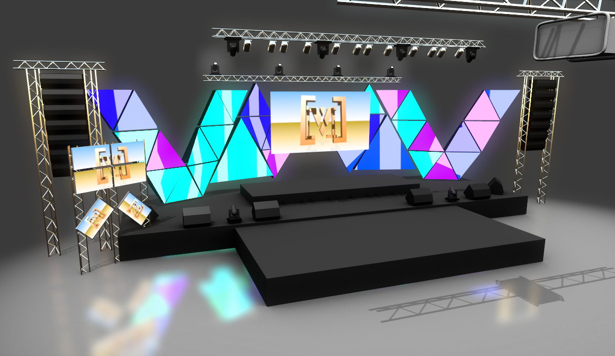
A Previs scene can be a range from a simple setup using one or several 2D Screens to complex 3D Scenes with several Multi GPU driven machines using all available outputs.
Ventuz previsualization capabilities have a the ability to cover:
- Simple screens - based on simple resolution settings
- LED Walls - each with a unique pixel pitch
- LED Wall Tiles - arranged in abstract shapes and rotations
- Movable screens or projectors
- Displays with bezel compensation
- Viewing a Previs Scene in Virtual Reality using Head Mounted Displays (VR-Headset)
Ventuz can use or import several kinds of geometry files. A stage setup that has been created in an external program can be imported to Ventuz and added to. Standard units in this 3D object file can be used inside of Ventuz to easily apply a screen or LED wall to the geometry that is imported, removing the guess work.
A Previs Canvas can be assigned to an output of Ventuz inside of the Render Setup Editor to view the Previs Scene in a physical Ventuz output.
While the preview inside of Ventuz is limited to 4096 when viewing inside of the Renderer Window, there is no limit when outputting from Ventuz; ie. not viewing in the Designer and is assigned to a Runtime. In this case, the resolution limit is the same as other rendered scenes, the max texture size of the graphics card: 16K.
How to Access
To create a Previs Scene, follow the How to create a previs scene guide.
Another great resource about the concept of a previs scene and using multi screens and multi outputs is the Multi-Screen/Output Workflow page.
Conclusion
From pre-production to the final setup, Previs can create a complete picture of how any setup can or will look, no matter how simple or complex.